Mda set-up, Caution – Oxmoor MDA-16 User Manual
Page 6
MDA BALANCED/UNBALANCED OUTPUT OVERVIEW
(Refer to Figure 3.0)
The MDA-16 and MDA-26 outputs may be independently
set for either balanced or unbalanced operation. In the
unbalanced configuration, pin 3 of the output connector is
grounded, and the maximum output level drops by 6 dB.
MDA-26 OUTPUT SOURCE OVERVIEW
(Refer to Figure 4.0)
The signal source for each MDA-26 output may be
independently selected: INPUT 1 and/or INPUT 2.
This capability greatly enhances the unit's flexibil-
ity, allowing it to assume a wide variety of signal
distribution configurations
. (See MDA CONFIGURA-
TION EXAMPLES, page 6.)
1. Disconnect the AC power cord.
2. Remove the screws that secure the top cover and set the
cover aside.
3. The BALANCED/UNBALANCED jumpers are located
on the circuit board next to their respective output con-
nector. The jumper is factory-installed in the balanced po-
sition.
4. Observing the positions marked on the circuit board,
remove the jumper and reinstall in the unbalanced posi-
tion.
5. Replace top cover and screws.
NOTE: In the unbalanced mode, use pin 2 as HOT and pin 3 as
COMMON. Pin 1 is to be used as SHIELD.
MDA-26 OUTPUT SOURCE SELECTION
1. Disconnect the AC power cord.
2. Remove the screws that secure the top cover and
set the cover aside.
3. The OUTPUT SOURCE jumpers are located on
the circuit board next to there respective input trim
pots. The jumpers are factory-installed with INPUT
1 and INPUT 2 both assigned to all outputs.
4. Observing the positions marked on the circuit
board, remove the jumper(s) and reinstall in the de-
sired positions.
5. Replace top cover and screws.
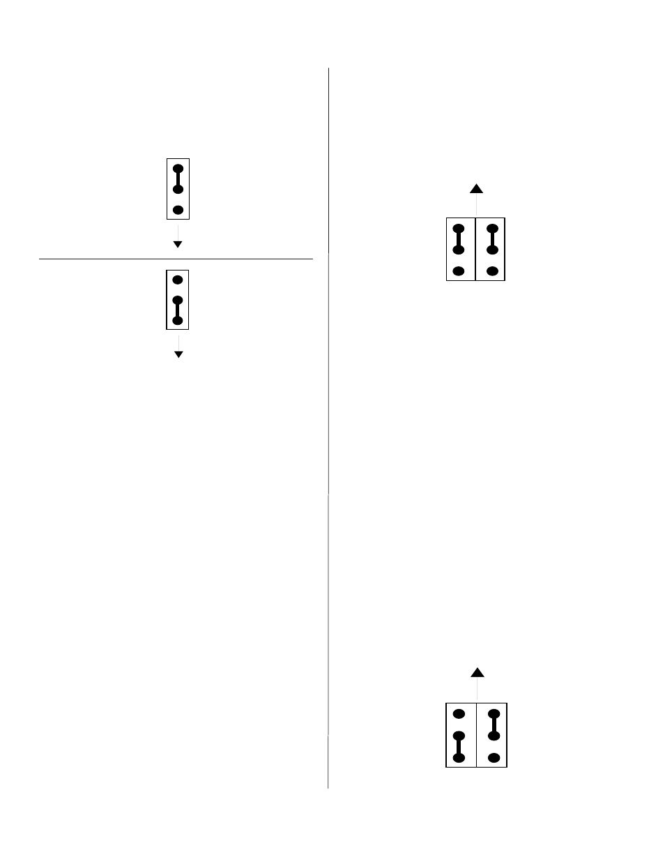
MDA-26 OUTPUT SOURCE SELECTION EXAMPLE
(Refer to Figure 4.1)
INPUT 1 is assigned to this output and INPUT 2 is
turned off to this output.
Figure 4.1: MDA-26 Source Selection Example
ON
OFF
CH 1
CH 2
Arrow Pointing to Front
Panel of MDA-26
ON
OFF
CH 1
CH 2
Figure 4.0: MDA-26 Source Selection
Arrow Pointing to Front
Panel of MDA-26
Balanced Set Up
Arrow Pointing to Rear
Panel of MDA
Unbalanced Set Up
Figure 3.0: Output Jumper Setup
Arrow Pointing to Rear
Panel of MDA
MDA BALANCED/UNBALANCED OUTPUT SELECTION
Internal jumpers are factory-installed to provide balanced
outputs. Figure 3.0 shows the proper jumper positions for
balanced or unbalanced operation. Correct internal jumper
placement ensures the corresponding output driver will
not be shorted to ground. (While an output short will not
harm the circuit, it may result in increased distortion and
crosstalk.) This procedure also simplifies output connec-
tions by allowing the use of standard cables in all cases.
Outputs may be reconfigured for unbalanced operation in
five simple steps:
CAUTION:
Hazardous voltages are present inside the
chassis. Before opening the case to gain access to the
printed circuit board, always remove the power from the
unit by disconnecting the AC power cord.
CAUTION:
Hazardous voltages are present inside the
chassis. Before opening the case to gain access to the
printed circuit board, always remove the power from the
unit by disconnecting the AC power cord.
Page 4
MDA SET-UP