Spot-1 specifications – Oxmoor SPOT-1 User Manual
Page 11
Page 9
SPOT-1 SPECIFICATIONS
Specifications subject to change without notice.
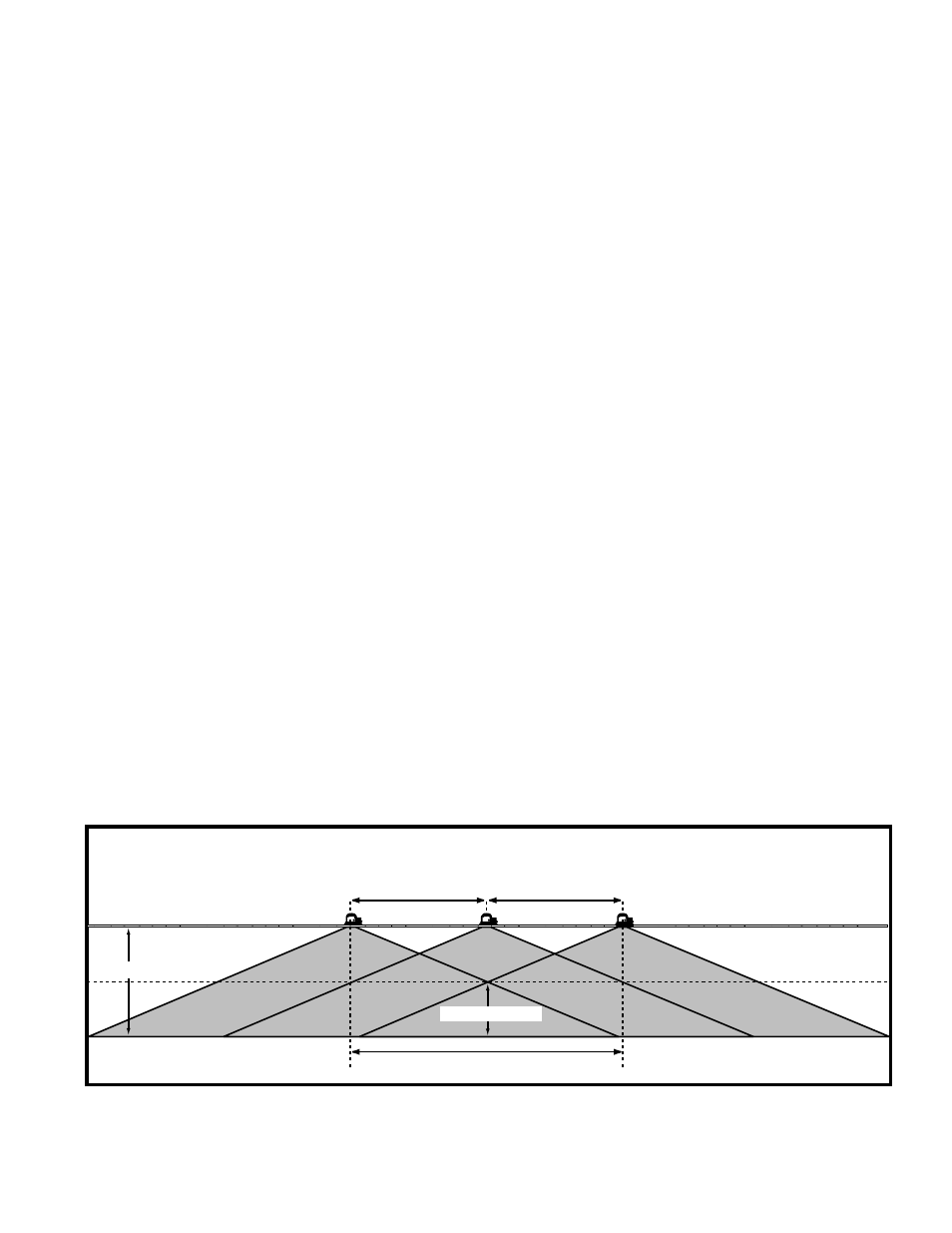
10' On Center
10' On Center
Receiver 4' Off Floor
Optimum Coverage Area
8' Ceilling
INPUT TYPE .................................................................................... RF
INPUT CONNECTOR ........................................................................ BNC
INPUT IMPEDANCE ......................................................................... 25 k ohms at 95 kHz
MAXIMUM CARRIER FREQUENCY .................................................... 3 MHz
MAXIMUM RF INPUT LEVEL WITH 50 OHM LINE TERMINATION ...... 3 V Peak to Peak (13.5 dBm)
NUMBER OF DIODES ....................................................................... 72
IR OUTPUT ...................................................................................... 1.5 W / Steradium, On Axis
WAVE LENGTH OF RADIATED INFRARED LIGHT ............................... 880 nm
AUTOMATIC ON/OFF FUNCTION, INTERNAL JUMPER SELECT ........ Carrier Detect for 95 kHz and 250 kHz
STORAGE TEMPERATURE ................................................................ 0
°
C to 70
°
C
OPERATING TEMPERATURE ............................................................. 10
°
C to 50
°
C
HUMIDITY ....................................................................................... 80% Max., Non-condensing
AC POWER ...................................................................................... 90-264 VAC, 35 Watts, 47 to 63 Hz
PACKAGING ..................................................................................... HALO Recessed 6-in. H7TH Housing
MOUNTING ..................................................................................... Ceiling Mount
DIMENSIONS ................................................................................... 203mm H x 279mm W x 356mm D
(8 in. H x 11 in. W x 14 in. D)
WEIGHT ........................................................................................... 2.4kg (5 lb. 3 oz.)
COVERAGE FOR CEILING INSTALLATION HEIGHT:
Single Channel with a Ceiling Height of ................................... 24 ft.
Optimum Radius 4 ft. from the Floor Surface ......................... 30 ft.
Maximum Radius a 4 ft. from the Floor Surface ...................... 45 ft.
Single Channel with a Ceiling Height of .................................. 12 ft.
Optimum Radius 4 ft. from the Floor Surface ......................... 20 ft.
Maximum Radius a 4 ft. from the Floor Surface ...................... 35 ft.
Single Channel with a Ceiling Height of .................................... 9 ft.
Optimum Radius 4 ft. from the Floor Surface .......................... 16 ft.
Maximum Radius 4 ft. from the Floor Surface ........................ 30 ft.
Single Channel with a Ceiling Height of ................................... 8 ft.
Optimum Radius 4 ft. from the Floor Surface .......................... 10 ft.
Maximum Radius 4 ft. from the Floor Surface ........................ 20 ft.
Side View Of Typical Ceiling Installation With Ceiling Height of 8 Feet
Figure 5.0: Typical Coverage Pattern