Introduction, Inspection, Description front panel – Supreme Audio SPA67 User Manual
Page 2: Rear panel, Connection, Operation
INTRODUCTION
Thank your for your purchase of the SupremeAudio SPA67 Microphone/Source Mixer.
The SPA67 is a single rack space audio mixer with three XLR inputs and four stereo RCA
source inputs. Talkover features have been included on Mic 1 and Source 4 for paging and
music priority functions.
INSPECTION
1. Unpack and inspect the SPA67 box and package.
If obvious physical damage is noticed, contact the carrier immediately to make a damage
claim.
2. For warranty information, and to register your warranty, please visit our website at
www.
SupremeProAudio.com.
DESCRIPTION
FRONT PANEL
Mic 1 - 3: Adjust the level of signal from the corresponding Mic Input.
clip 1 - 3: LED indicating overload in the channel. The LED lights 3dB below clipping.
TONE 1 - 3: Adjusts the frequency content of the signal in the channel. When the control is
turned counter-clockwise, the high frequencies are cut, when the control is turned clock-
wise, the low frequencies are cut.
IN 1: 3.5mm Input jack - resistor mixed to Source Input 1.
Source 1 - 4: Adjust the volume of input from the RCA Source Inputs, and the 3.5mm in.
Bass: Adjusts the low frequencies of the Source signals only.
Treble: Adjusts the high frequencies of the Source signals only.
Master Level: Adjusts the overall volume of the SPA67 Main Outputs.
pwr: LED indicating power is applied to the SPA67 and the unit is on.
REAR PANEL
120V
AC 50/60Hz
MODEL SPA67
MADE IN USA
www.SupremeProAudio.com
SERIAL NUMBER
67 -
WARNING:
DO NOT EXPOSE
THIS EQUIPMENT TO RAIN OR
MOISTURE.
RISQUE DE CHOC - NE PAS ENLIVER
DUCK
SENSITIVITY
Mic 1 - 3: XLR inputs for dynamic or condenser microphones, or balanced line-level signals.
Mic/Line Switch: Pads the XLR Mic input by 30 dB when pressed in.
DIP SWITCH: Contains the small switches for engaging Mic 1 - 3 phantom power, the
priority (Talk Over) functions, and the Mono/Stereo select.
MIC INSERT: 1/4” TRS insert jack for adding external processing to the Mic signals. Tip =
send, ring = return.
SOURCE INPUTS: Stereo RCA jacks, Channels 1 - 4, for connection to stereo sources
such as AM/FM tuners, cassette players, cd players, or video players.
RECORD OUT: Stereo RCA jacks, contains all mixed signals before the Remote Volume
jack, and Master Level control.
SPARE: This RCA jack is not connected.
MUTE: RCA jack for connection to a tip-to-ground muting circuit.
REMOTE VOLUME: 1/4” TS jack for connection to a remote potentiometer for master vol-
ume control. 20K Ohm audio taper potentiometer is recommended.
MAIN OUTPUTS: 1/4” TRS balanced Right and Left Outputs.
DUCK SENSITIVITY: Adjusts the level of input signal required for ducking to occur. NOTE:
The release time is effected by this setting, plus the level of input signal - the higher the
input signal, the longer the release time.
IEC POWER INPUT: Connect to the IEC power cable - and properly grounded ac outlet.
CONNECTION
Connect low impedance microphones to the Mic inputs. If a paging microphone is being
used, connect it to Mic Input 1 so it may be used with the Talk Over function. Connect
source signals such as CD players, cassette players or video players to the RCA Source
Inputs. If a jukebox is being connected, and you want its signal to mute the other source
signals, connect it to Source input 4. Connect 3.5mm sources to the front panel input.
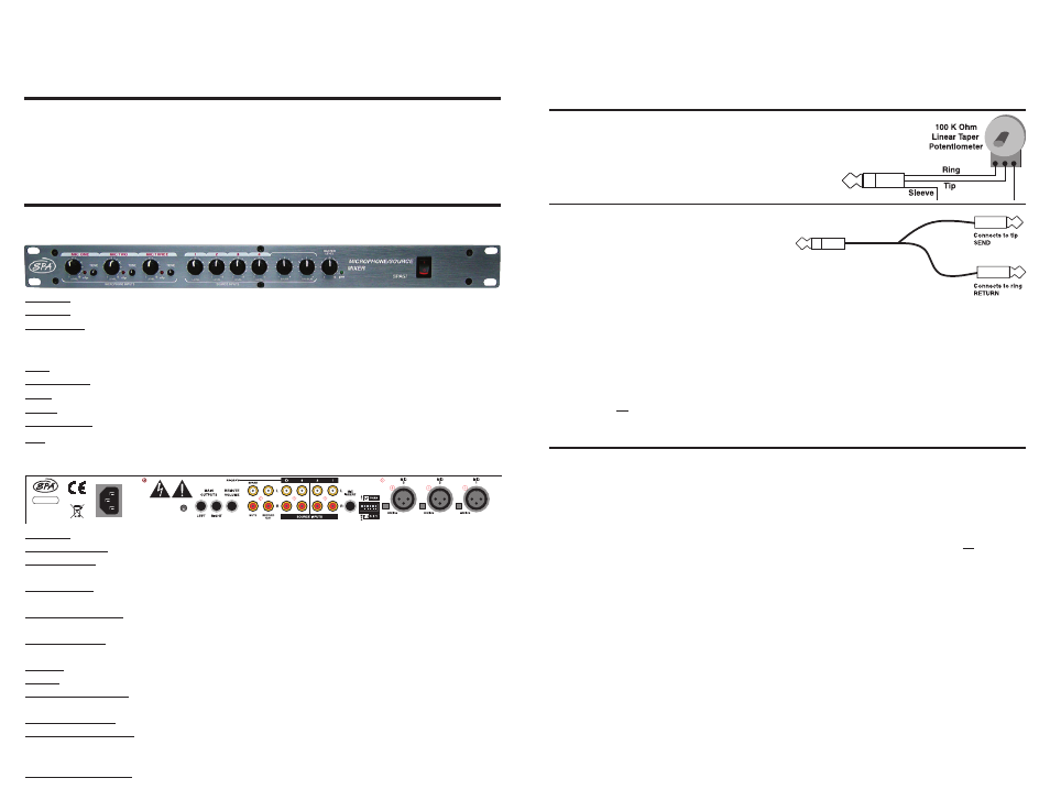
Remote Volume Control
To control the overall volume of the SPA67 in a remote location, wire
a 100K ohm Linear Taper potentiometer to a 1/4” Tip-Ring-Sleeve
plug as shown here.
Mic Insert
To connect a signal processor to the SPA67
microphone signal(s), use an insert plug, or
cable wired as shown here.
Connect the Main Right and Left outputs to
your power amplifiers. The SPA67 output jacks
will accommodate balanced or unbalanced connections. For unbalanced operation use
1/4” Tip Sleeve jacks, for balanced operation use 1/4” Tip Ring Sleeve jacks. If a 1/4” TRS
to XLR cable is needed, wire the Tip of the 1/4” jack to pin 2 of the XLR, the Ring to pin 3,
and the Sleeve to pin 1 or the shield.
Mute
To mute all audio, connect an RCA plug to your muting circuitry. When the tip is shorted to
the ground - all audio is muted.
Connect the SPA67 to a properly grounded AC outlet.
OPERATION
DIP SWITCH SETTINGS
- If a microphone requires phantom power, move the Mic channel’s corresponding PHAN
DIP switch to the down position. This applies 12 volts dc phantom power to the indicated
microphone.
- Talkover switch 1 (T.O. 1), when in the down position, all program material on all inputs
will be “ducked” or muted when a signal is present at Mic 1.
This function is used for paging.
- Talkover switch 2 (T.O. 2), when in the down position, Source 1,2, and 3 will be “ducked”
or muted by the signals at Source 4.
This function is for jukebox priority. With a jukebox connected to Source input 4, and the
Talkover switch 2 on (down), the other Source input signals such as background music, will
be muted and only the jukebox will be heard.
- The Mono/Stereo switch selects the output mode. When the switch is up, the unit is in
stereo mode. When the switch is down, the stereo signals are mixed to mono and sent to
both the Right and Left Main output jacks. Either jack can be used as a mono output.
Adjust the Microphone levels for maximum input signal without clipping, and for a comfort-
able listening level. Adjust each Source level for a desired listening level.
Tech
nical Support: 1-800-445-7398 or 1-603-876-3636
To Mic Insert