Vectronics VEC-422K User Manual
Page 12
VEC-422K Owner's Manual
SCA Decoder Kit
10
Resistor Installation:
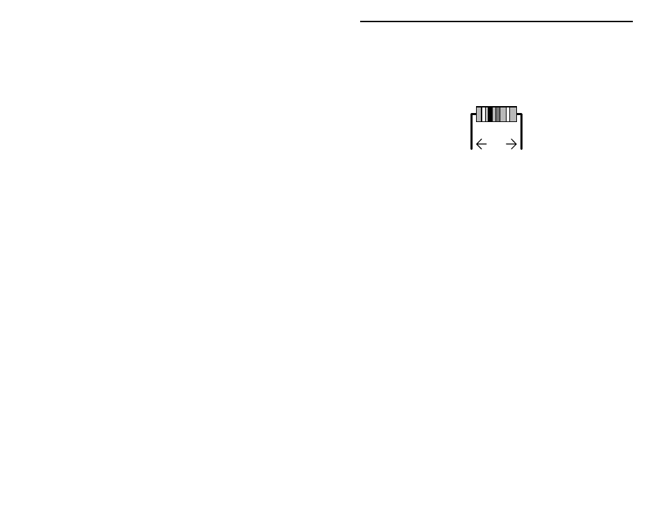
Begin assembly by installing the ¼-watt fixed resistors. Because these are all 5-
percent tolerance ending with a fourth gold color band, you need only read the
first three bands of the color code during the following steps. All resistor leads
should be formed as shown below. Install and solder resistors at the following
locations:
.4"
NOTE: the fourth resistor color band is for tolerance, and is not called out in
the following steps.
! ! 1. Locate the 15-ohm resistor (brown-green-black). Install and solder at
location R15.
Locate the three 510-ohm resistors (green-brown-brown). Install and solder at
the following locations:
! ! 2. R1
510-ohm resistor (green-brown-brown)
! ! 3. R3
510-ohm resistor (green-brown-brown)
! ! 4. R5
510-ohm resistor (green-brown-brown)
Locate the three 4.7K-ohm resistors (yellow-violet-red). Install and solder at the
following locations:
! ! 5. R6
4.7K-ohm resistor (yellow-violet-red)
! ! 6. R10
4.7K-ohm resistor (yellow-violet-red)
! ! 7. R13
4.7K-ohm resistor (yellow-violet-red)
! ! 8. Locate the 10K-ohm resistor (brown-black-orange) . Install and solder
at location R4.
! ! 9. Locate the 18K-ohm resistor (brown-gray-orange). Install and solder
at location R8.
Locate the three 24K-ohm resistors (red-yellow-orange). Install and solder at the
following locations:
! ! 10. R11
24K-ohm resistor (red-yellow-orange)
! ! 11."R12
24K-ohm resistor (red-yellow-orange)
! ! 12."R14
24K-ohm resistor (red-yellow-orange)