Integrating the controller pcb – Zytronic ZXY200 User Manual
Page 11
Integration Manual - Issue 1
Zytronic Projected Capacitive ZXY200/300
®
Multi Touch Controller & Sensor
11
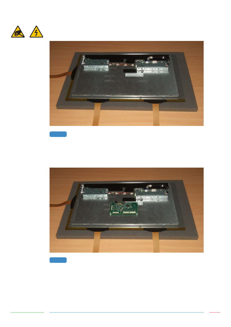
INTEGRATING THE CONTROLLER PCB
The components on the rear of the LCD should be arranged to allow a suitable space for the controller
PCB, as shown in Figure 5.
REAR OF LCD READY FOR CONTROLLER MOUNTING
The controller PCB should be positioned so that all three flexible cables from the sensor can
comfortably reach their respective ZIF sockets without crossing over other cables or PCBs. There should
also be sufficient space around the power and USB sockets to attach the cables. Ideally avoid placing
the controller within ~30mm of other PCBs and cables, as shown in Figure 6.
CONTROLLER POSITION ON REAR OF LCD
The Flexible cables plug into the ZIF sockets as shown in Figure 7. When viewing from the rear of the
LCD with the sensor orientated as shown in Figure 6, the flexible cable attached to the left of the
long edge of the sensor should connect to Transmit 1, and the flexible cable attached to the right of
the long edge of the sensor should connect to Transmit 2. The single flexible cable attached to the
short edge of the sensor should connect to Receive 1. No connection should be made to Receive 2 for
standard sensor designs.
FIGURE 5
FIGURE 6