Installation – American Time AllSync Plus User Manual
Page 11
11
© American Time
AllSync Plus Clock Installation
& Operation Manual
Glossary
Appendix B LED
Illumination
Appendix A
Specifications
Tr
oubleshooting
General
Operation
Installation
Intr
oduction
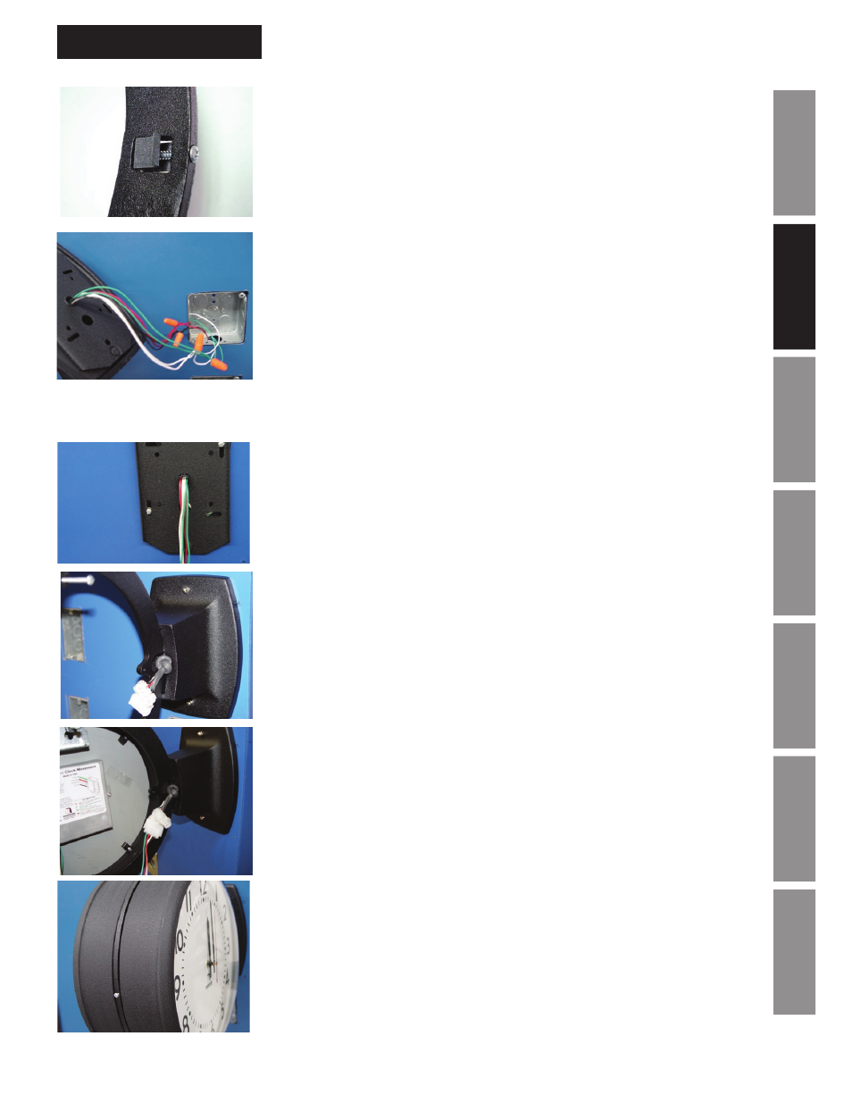
Installation
5. Attach mounting clips by threading the 1
1
/
4
" screws included through
them in each of the three positions. Do not completely tighten, they
should be loose at this point.
6. Using UL approved wire nuts, make connections between flying leads
and wiring inside electrical box.
a. Black wire should be connected to hot (run) wire from the master.
b. Red wire should be connected to the correction line from the
master clock.
c. White wire should be connected to the neutral line.
d. Green wire should be connected to earth ground.
Note: All wiring connections should be made in accordance to local and
national electrical codes
7. Attach box plate to electrical box.
8. Attach double dial ring to box plate using acorn style nuts.
9. Hang one side of the double dial clock on mounting ring using protruding
screw and connect clock wires to one of the wall ends.
Note: The knot in the wall side wire harness may block clock installation. By
simply pulling it away from ring base about half an inch will provide adequate
space to install both clock sides.
10. Connect remaining side of double dial clock to remaining wire harness
wall end and hang on remaining screw.
11. Tighten mounting clips installed in step 5 to firmly secure both side of
double dial clock.