American Time Synchronous Wired and Electronic Movement User Manual
Page 2
American Time - 140 3rd Street South - PO Box 707 - Dassel, MN 55325-0707
2
Hourly Correction
See Fig. 59
1. Pick-up ratchet R is continuously rotating at a rate
of 1rpm. this is due to the drive applied to it via ratchet
drive gear Q, by pinion A. Except during a correction
cycle, pawl throwout lever T prevents pick-up pawl S
from engaging ratchet R.
See Fig. 63A on Page 3
2. From 57:54 to 58:02 of each hour (master clock
time), a correction signal that is initiated by the master
clock causes the correction solenoid to energize.
3. When the solenoid energizes, the corrective lever
(mounted to the solenoid leaf) engages the pick-up
ratchet.
4. The corrective lever then begins to move upward.
After 6 seconds it lifts the pawl throw-out lever and
thereby releases pick-up pawl S (Fig. 59).
See Fig. 59
5. Pick-up pawl S engages ratchet R. Stop disc
assembly U then rotates at the same speed as ratchet R.
6. As stop disc U rotates, pick-up spring V slides
around minute hand setting disc W. When the spring
engages the slot in disc W. disc W then rotates at the
same speed as ratchet R (see NOTE at the top of the
page). Also, as disc U rotates, the projection end of
aligner lever X is placed into the orbit of the projection
on friction coupling assembly C. When the projections
meet, the normal drive of the movement is stopped. (The
projections will not meet if the secondary is “on time”
with the master clock)
7. Pinion Y, which is fixed to disc W, then drives
intermediate gear L. Gear L drives minute drive pinion
J and minute hand shaft H. (Pinion M, which is fixed to
gear L, drives hour gear P and hour hand shaft N) This
drive causes the secondary to advance at a rate 60
times normal speed.
8. At the 59th minute (master clock time), stop disc
assembly U has completed one revolution. Throwout
lever T, which returns to its original position eight
seconds after the initiation of the correction cycle,
causes pick-up pawl S to disengage from ratchet R. the
minute hand of the secondary should be on the 59th
minute, and the second hand on the 00 second mark.
NOTE: The normal drive of the secondary causes minute
hand setting disc W to rotate. If the secondary is “on
time” with the master clock, the slot in the setting disc
will have advanced to a point where the pick-up spring
will make a complete revolution without engaging the
slot. If this is the case, minute hand setting disc W will
not be speeded up to the speed of ratchet R. the normal
drive of the secondary will continue to operate the
movement.
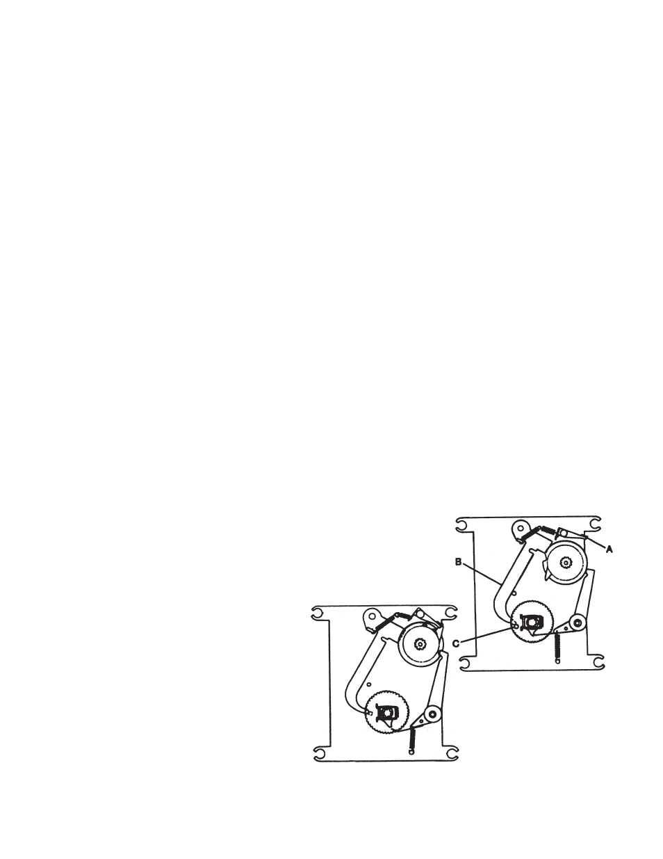
12 Hour Correction (Figs. 60A & 60B)
A 12-hour correction cycle is accomplished merely by
allowing the movement to go through more than one
hourly correction cycle. This is accomplisher as follows:
1. From 5:57:54 to 5:58:08 AM & PM (master clock
time), a 12 hour correction signal that is initiated by the
master clock causes the correction.
2. After 6 seconds the movement is placed into hourly
correction cycle. Since the solenoid remains energized
for a total of fourteen seconds, throwout lever A is lifted
high enough to be latched into a raised position by
12 hour latch lever B (see NOTE below). This causes
the movement to advance (in the same manner as
previously explained for hourly correction( at a rate 670
times normal speed until latch lever B rides onto stud
C and allows throwout lever A to return to its normal
position.
NOTE: If the movement is on the correct hour, latch
lever B will be in the position illustrated by Fig. 60B and
therefore prevent throwout lever A from being latched.
Therefore, only one hourly correction cycle would be
completed.
Fig. 60A
Fig. 60B