Rear panel description, Menu tree, Warranty – Analog Way TRK-800 User Manual
Page 4
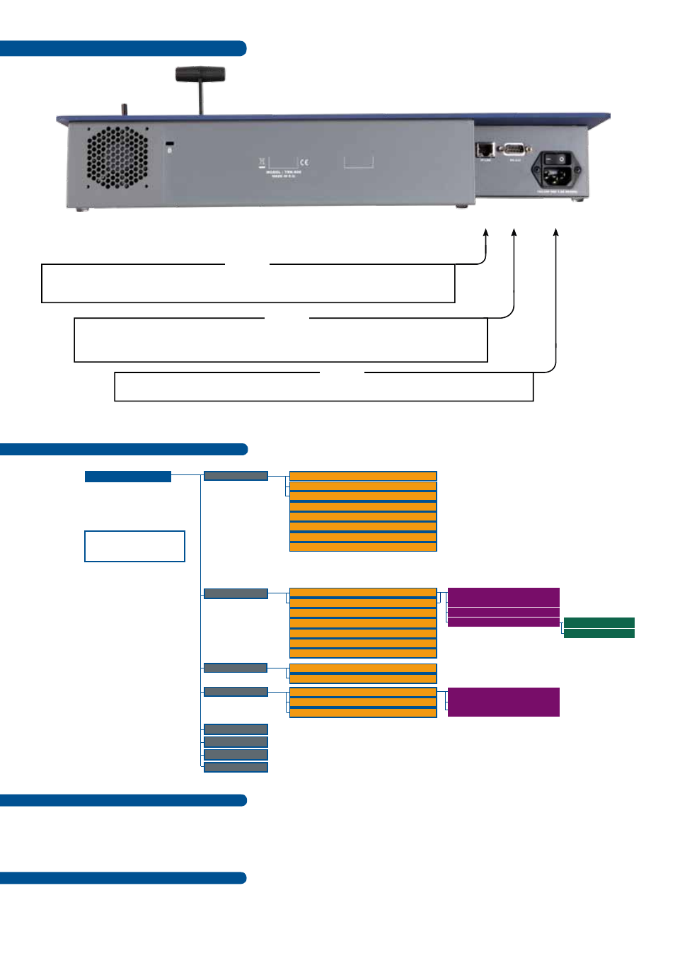
Rear Panel Description
Going further with the TRK-800
Please check the User Manual and our website for further information:
www.analogway.com
Version : 3.0 - 09/01/2012
Code : 140117
RS-232 PORT: Connect the RS-232 connector to the serial port of the computer with the update
cable supplied (DB9 F/F cross cable). Please follow instructions of the software for an update.
RJ-45 Connector: Connect the TRK-800 to a 10/100 BT Ethernet LAN using this female RJ-45
connector : Used to control the switcher and also to upgrade the TRK-800.
AC Power connector: Plug a power supply cord: Internal, universal, 100-240 VAC, 50/60 Hz, 1.5A.
RS-232
AC
RJ-45
Menu Tree
Versions
LAN setup
Key locking
Prog. keys
LCD brightness
Key brightness
Standby
Default values
(L2)
Version: 1.00 BETA
I3=xxxx I4=xxxx
Netmask
Boot: 1.00 BETA
O=0000
Device 1 Setup
CS2=xxxx
Device 3 Setup
I1=xxxx I2=xxxx
CS1=xxxx
Device 2 Setup
CS3=xxxx
Default Setup
(L2)
TRK-800 address
All
Fade
Gateway adress...
Menus
user 1
user 2
Type
(L3)
Remote address
Direction
(L3)
Remote port
Effect duration
Local port
(L1)
Protocol
TCP
uDP
TRK-800 CONTROL
(L1) UDP only
(L2) Confirmation asked
(L3) Only for User1& User2
Warranty
All
Analog Way
products have a 3 year warranty on parts and labor, back to factory, but do not include faults resulting from
user negligence, special modifications, electrical surges, abuse (drop/crush), and/or other unusual damage.
Please note: The included carrying case and protective foam is not covered under warranty.
NOTE : The updater files are available on our web site :
http://www.analogway.com
The settings for Serial and Ethernet connections are similar to the connected device.