Apantac MT HOOD Series Touch Screen User Manual
Mt hood series, User guide
MT HOOD Series
Touch Screen
Extenders w/Audio
User Guide
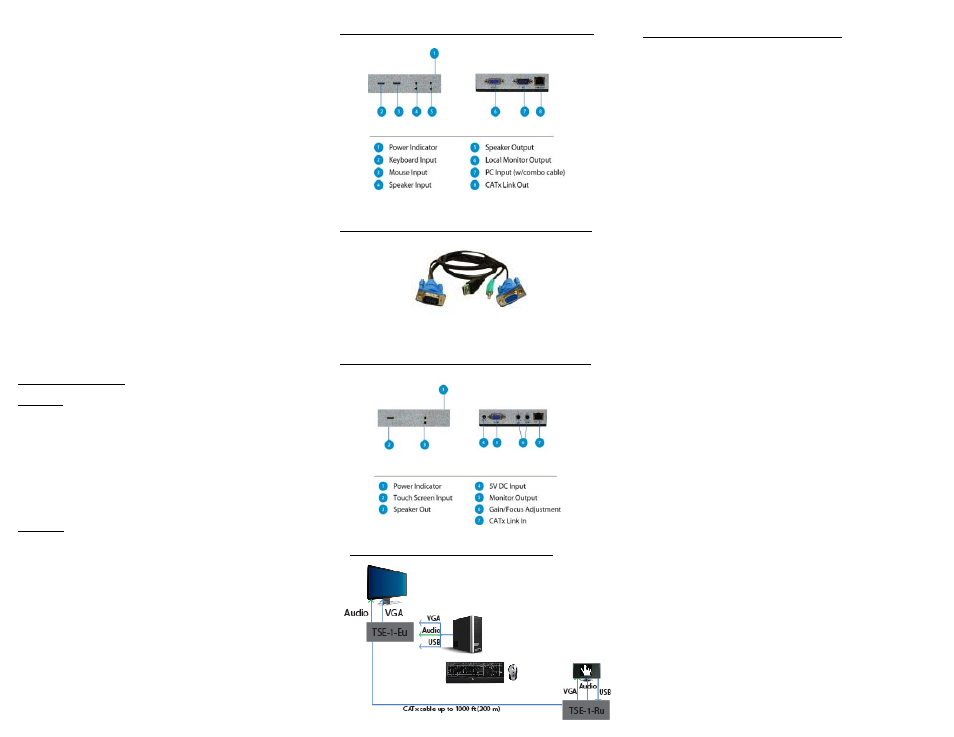
TSE-1-Eu - VGA + Audio + USB Touch Screen Extender
TSE-1-Ru - VGA + Audio + USB Touch Screen Receiver
DVI-1-EM – Single Port DVI Extender with Monitor Output
Version 1.0
Dated: December, 2009
© 2009 Apantac LLC - All rights reserved
The contents of this document are provided in connection with Apantac LLC (“Apantac”)
products. Apantac makes no representations or warranties with respect to the accuracy
or completeness of the contents of this publication and reserves the right to make
changes to specifications and product descriptions at any time without notice.
What’s in the Box
TSE-1-Eu
1. Transmitter (TSE-1-Eu) x 1
2. 3 ft (1m) VGA+Audio+USB combo cable
3. Manual x 1
4. Mounting plate
5. DC 5V 1A power supply is option for the transmitter
TSE-1-Ru
1. Receiver (TSE-1-Ru) x 1
2. DC 5V 1A power supply
3. Mounting plate
TSE-1-Eu - VGA+Audio+USB Touch Screen Extender
CBK1510 - VGA+Audio+USB Combo Cable (3 ft/1m)
TSE-1-Ru - VGA+Audio+USB Touch Screen Receiver
TSE-1-Eu / TSE-1-Ru Connection Diagram
INSTALLATION AND OPERATION
STEP 1: Installing the Transmitter
1. For first time installation, please turn the power off on
the PC
2. Connect the combo cable (CBK1510) to the appropriate
ports on the PC
3. Connect the HDB-15 VGA connector to the PC in port of
the TSE-1-Eu
4. Connector the local monitor and speaker to VGA out and
Audio out
5. The TSE-1-Eu is powered by the USB connector on the
combo cable (CBK1510). If your PC does not provide
appropriate power from the USB port, then you will need
to purchase the optional 5V power supply
6. When the TSE-1-Eu is receiving appropriate power, the
yellow LED on the System Link RJ-45 connector will be
on (without flashing).
7. Turn on the PC, the green light on the System Link RJ-45
connector will be on (without flashing), when proper
VGA single is received.
8. The local monitor and speaker should also be working
properly.
STEP 2: Installing the Receiver
1. Place the receiver in the proper location
2. For optimal result, Apantac recommends Belden
1700A, Belden 1752A, Belden 1872A, Belden
7989R, Belden 2988R or similar cables.
3. Connect the USB cable between the USB port of the
touch screen and port on the TSE-1-Ru marked Touch
Panel
4. Plug in the power supply
5. When the TSE-1-Ru is receiving appropriate power, the
yellow LED on the System Link RJ-45 connector will be
on (without flashing).
6. Connect the VGA and speaker output from the touch
screen to the appropriate inputs of the TSE-1-Ru
STEP 3: Connect the CATx UTP cable
1. Connecting the CATx cable
2. The CATx UTP should comply with 568B.
3. Connect the UTP cable to both TSE-1-Eu and TSE-1-Ru’s
System Link RJ-45 port.
4. The Green LED should be lit, when proper link is estab-
lished.
STEP 4: Final STEP
1. You should now be able to operate the touch screen
remotely.
2. To optimize the image quality, Focus and Gain can be
adjusted.