Figure 2 – led output meter and link switch, Led output meter, The link switch – ART Pro Audio Pro VLA II - Two Channel Vactrol-based Compressor User Manual
Page 9
8
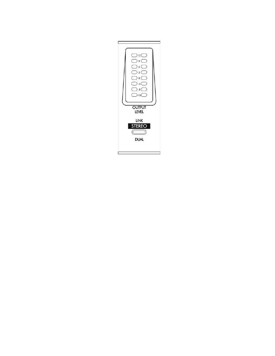
FIGURE 2 – LED Output Meter and Link Switch
LED Output Meter
This meter displays both average and peak levels of the output signal. The LED labels indicate how far the
output is away from full maximum output in dB.
In each bargraph, a single LED is held on for a little over one second, displaying the peak level. Some peaks
may not be audible, but can cause clipping in equipment following the Pro VLA II
.
Average levels are indicated by a histogram style display. The average levels displayed are similar to the VU
meter when it is set to monitor the output level.
“0” on the meter corresponds to an output level of +16dBu when the I/O level switch is in the +4 mode. When
in the “-10” mode, this level becomes +6dBu.
The Link Switch
The two channels of the Pro VLA II
can be configured for stereo operation by depressing the LINK switch.
Link Mode ties the output attenuation of both channels together onto the CH1 OUTPUT LEVEL knob, and
moves all control over “Attack” and “Release” times to the CH1 set of controls. The CH2 OUTPUT LEVEL
control becomes an output balance control. Link Mode ensures that each channel of the stereo input signal is
processed identically to prevent any shifting or distortion of the stereo image.
Bypass and meter-source select switch functions remain unchanged in “link” mode.