3 thermal requirements, 4 thermally significant components, Table 2-4 – Artesyn MVME4100ET Single Board Computer Installation and Use (June 2014) User Manual
Page 29: Thermally significant components, Hardware preparation and installation
Hardware Preparation and Installation
MVME4100ET Single Board Computer Installation and Use (6806800K76F)
29
2.3.3
Thermal Requirements
The MVME4100ET module requires a minimum air flow of 14 CFM uniformly distributed across
the board, with the airflow traveling from the heat sink to the PMC2 site, when operating at a
71°C (160 °F) ambient temperature.
2.3.4
Thermally Significant Components
The following table summarizes components that exhibit significant temperature rises. These
are the components that should be monitored in order to assess thermal performance. The
table also supplies the component reference designator and the maximum allowable
operating temperature.
You can find components on the board by their reference designators as shown in
and
. Versions of the board that are not fully populated may not contain some of
these components.
The preferred measurement location for a component may be junction or case as specified in
the below table. Junction temperature refers to the temperature measured by an on-chip
thermal device. Case temperature refers to the temperature at the top, center surface of the
component.
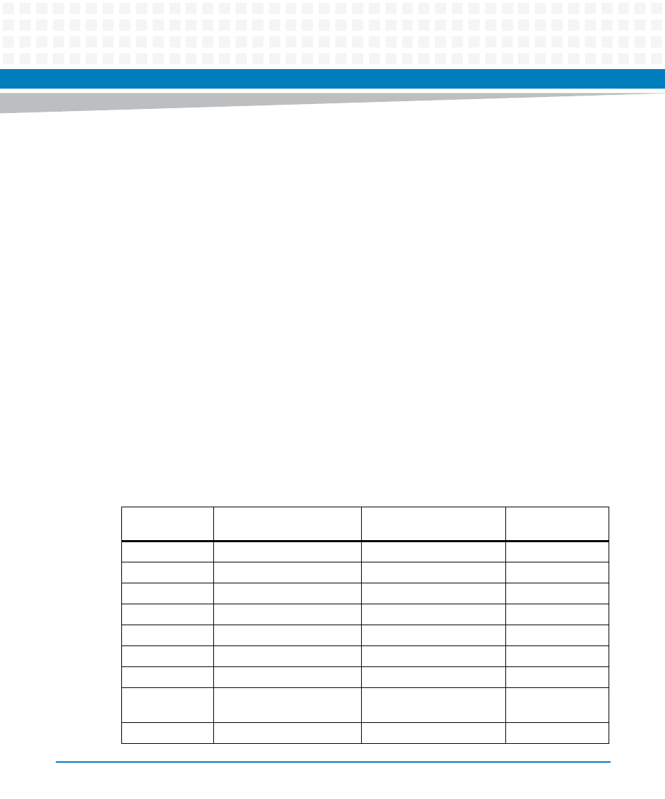
Table 2-4 Thermally Significant Components
Reference
Designator
Generic Description
Maximum Allowable
Component Temperature
Measurement
Location
U12
Processor
105 °C (+221 °F)
Junction
U4, U27
Gb Ethernet Transceivers
125 °C (+257 °F)
Junction
U66
MRAM
115 °C (+239 °F)
Junction
U24
VME Bridge
122 °C (+251.6 °F)
Junction
U22, U25
PCI-X to PCI-X Bridge
125 °C (+257 °F)
Junction
U67
PLD
90 °C (+194 °F)
Junction
U21
CPLD
85 °C (+185 °)
Junction
U2, U34, U35,
U36
Transceivers
150 °C (+302 °F)
Junction
XJ1
DDR2 SDRAM
85 °C (+185 °)
Case