Controls, leds, and connectors – Artesyn MVME7100ET Single Board Computer Installation and Use (June 2014) User Manual
Page 54
Advertising
Controls, LEDs, and Connectors
MVME7100ET Single Board Computer Installation and Use (6806800K87E)
54
9
INTD#
PCI_RSVD
10
11
GND
+3.3Vaux
12
13
CLK
GND
14
15
GND
PMCGNT1#
16
17
PMCREQ1#
+5V
18
19
+3.3V (VIO)
AD31
20
21
AD28
AD27
22
23
AD25
GND
24
25
GND
C/BE3#
26
27
AD22
AD21
28
29
AD19
+5V
30
31
+3.3V (VIO)
AD17
32
33
FRAME#
GND
34
35
GND
IRDY#
36
37
DEVSEL#
+5V
38
39
GND
LOCK#
40
41
PCI_RSVD
PCI_RSVD
42
43
PAR
GND
44
45
+3.3V (VIO)
AD15
46
47
AD12
AD11
48
49
AD09
+5V
50
51
GND
C/BE0#
52
53
AD06
AD05
54
55
AD04
GND
56
57
+3.3V (VIO)
AD03
58
59
AD02
AD01
60
61
AD00
+5V
62
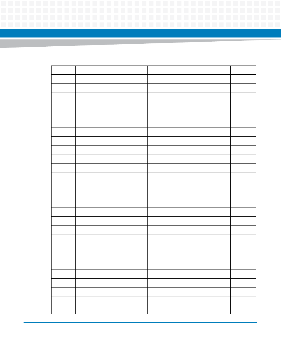
Table 3-5 PMC Slot 1 Connector (J11) Pin Assignments (continued)
Pin
Signal
Signal
Pin
Advertising