Dpa four series user manual, Rear panel features – ATEIS DPAfour125 User Manual
Page 5
DPAfour Series User Manual
www.ateis-europe.com
Page 5 of 11
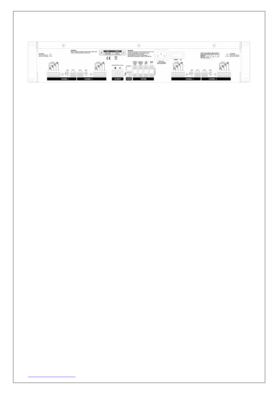
4. Rear panel features
AC Power Inlet:
The 3 pin IEC connector is located in the centre of the amplifier rear panel. It accepts a standard mains
power lead fitted with an IEC connector.
AC/DC Fuse Receptacles:
Both AC and DC power inputs are protected by means of electronic fuses. There are no serviceable parts
inside of the amplifier case.
Power Switch:
The power switch is located next to the power inlet on the rear panel. When the power switch is in the “ON”
position, the front panel power LED will be lit.
24VDC battery backup connector:
The DPAfour amplifier can be operated with battery backup. The connector is located on the central part of
the amplifier rear panel. This 24VDC power supply can be used where AC power is not available or
according to EN54 as a secondary supply. When in use, the front panel Power LED will activate in addition
to the front panel DC LED.
CAUTION!
If connected directly to a battery unit, this connection should be externally fused with
50A max.
This is not required when connected to the Ateis BECS150 Charger and Supply unit
Channel 1-4 Audio Output:
For each amplifier channel, there is a dedicated Audio Output connector for connection of a single selection
from a 4Ohm loudspeaker load or one of a 50V, 70V or 100V line loudspeaker load not to exceed the rating
of the amplifier output. For each load type, the Com point is the –ve terminal. The 4Ohm, 50V, 70V and
100V are the +ve terminals for each load type.
Channel 1-4 Inputs:
For each channel, there is a Euro terminal block balanced input. Each input offers gain adjustment as
required.
General Fault Output Contact:
The fault contact indicates an amplifier fault by giving an opening contact. (NC)
Service Request Output Contact:
The Service Request contact indicates that maintenance is needed. This is indicated by giving an opening
contact. (NC)
Lamp Test Input Contact:
By closing this input contact, all LEDs on the front display of the amplifier will activate.
Spare Input Contact:
For future use.
Configuration switches: