Spa series rear panel features – ATEIS SPA 2120 User Manual
Page 7
SPA series
Page 7 of 11
Temp.:
If the device internal temperature exceeds 95 degrees C, the TEMP LED will light and the pre-amp will stop working
until the temperature falls below 95 degrees C. The pre-amp will come back to a working state automatically. To
avoid temperature failure, please insert an external fan to the rack system.
DC:
The DC LED indicates that the SPA amplifier is powered by a 24VDC power supply.
Power:
The Power LED indicates the ON/OFF status of the SPA amplifier.
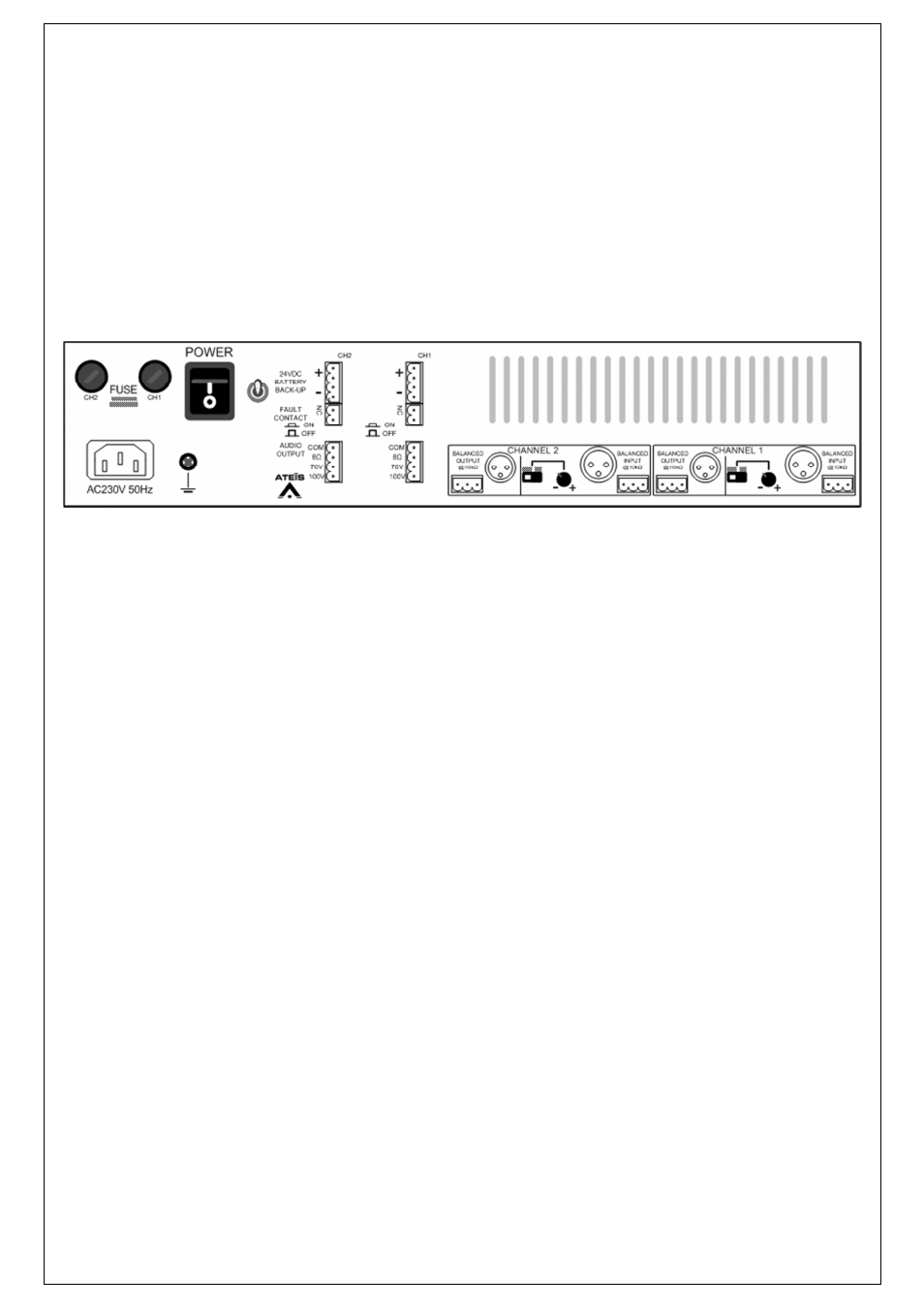
6.
SPA Series Rear Panel Features:
AC Power Inlet:
The 3 pin IEC connector is located on the left of the amplifier’s rear panel. It accepts a standard mains power lead
fitted with an IEC connector.
DC Fuse Receptacles:
Two DC fuse receptacles are located on the left of the amplifier’s rear panel. To access each fuse, unscrew the cap
with a screwdriver. For 115 V operations please use T2.5A fuses. For 230 V operations please use T1.25A fuses.
Power Switch:
The power switch is located at the left of the rear panel and is a two position switch. Pushing up the power switch (I
is pushed) will power on the device, pushing it down (0 is pushed) will power it off. When the power switch is on the
I position, the front panel power LED will be lit.
Indicator switch:
The small switch besides the Power switch is added to disable the local indicators on the SPA’s front.
Disabling the indicators is mandatory to make the total system compliant to the EN54-16.
Channel 1/2 24VDC battery backup connector:
The SPA amplifier can be operated with battery backup. Use the channel 1 and channel 2 “24VDC Battery Backup”
connector to do so. These connectors are located on the upper part of the channel connectors on the rear panel.
This 24VDC power supply can be used where no AC power is available. When in use, the front panel Power LED
will be lit as well as the front panel DC LED.
Fault Contact:
The fault contact indicates an amplifier fault by an opening contact.
Channel 1/2 Audio Output:
For each amplifier channel, there is a dedicated Audio Output connector for connection of either 8 Ohm speakers,
75V speakers or 100V speakers. For the 8 Ohm connection and if you are using more than 1 speaker, please
ensure that speakers are wired in a way that the total impedance load is between 8 Ohm and 16 Ohm. The Com
point is the – terminal and 8 Ohm, 75V and 100V are the + terminals.
Channel 1/2 Inputs:
For each channel, there is an XLR balanced input and a Euro-terminal block balanced input. Each input can be gain
adjusted to suit the user’s needs. The On/Off gain switch can instantaneously bypass the gain controller and set the
channel gain amplifier to maximum.