Basler Electric BE1-11 Modbus Protocol User Manual
Page 60
54
9424200774 Rev B
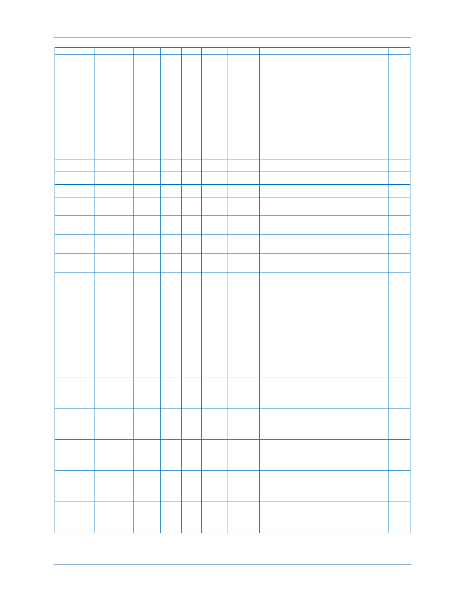
Register Table
BE1-11
Name
Description
Register
Type
Bytes Writable
Unit
Range
Style
Analog Output
Config 7
Parameter
Selection
18600
Uint32 4
R W
n/a
VA=0, VB=1, VC=2, VAB=3, VBC=4, VCA=5,
3V0=6, V1=7, V2=8, IA-1=9, IB-1=10, IC-1=11, 3I0-
1=12, I1-1=13, I2-1=14, IG-1=15, IA-2=16, IB-2=17,
IC-2=18, 3I0-2=19, I1-2=20, I2-2=21, IG-2=22,
Analog Input 1=21, Phase Frequency=23, Aux
Frequency=24, Power Factor=25, Real Power=26,
Imaginary Power=27, Apparent Power=28, Analog
Input 1-1=29, Analog Input 1-2=30, Analog Input 1-
3=31, Analog Input 1-4=32, Analog Input 2-1=33,
Analog Input 2-2=34, Analog Input 2-3=35, Analog
Input 2-4=36, RTD 1-1=37 RTD 1-2=38, RTD 1-
3=39, RTD 1-4=40, RTD 1-5=41, RTD 1-6=42, RTD
1-7=43, RTD 1-8=44, RTD 1-9=45, RTD 1-10=46,
RTD 1-11=47, RTD 1-12=48, RTD 2-1=49, RTD 2-
2=50, RTD 2-3=51, RTD 2-4=52, RTD 2-5=53, RTD
2-6=54, RTD 2-7-55, RTD 2-8=56, RTD 2-9=57,
RTD 2-10=58, RTD 2-11=59, RTD 2-12=60
FGIMT
Analog Output
Config 8
Type
18602
Uint32 4
R W
n/a
Voltage=0
Current=1
FGIMT
Analog Output
Config 8
Parameter
Minimum
18604
Float
4
R W
n/a
-199999.8
FGIMT
Analog Output
Config 8
Parameter
Maximum
18606
Float
4
R W
n/a
-199999.8
FGIMT
Analog Output
Config 8
Output
Current
Minimum
18608
Float
4
R W
Milliamp
4 - 20
FGIMT
Analog Output
Config 8
Output
Current
Maximum
18610
Float
4
R W
Milliamp
4 - 20
FGIMT
Analog Output
Config 8
Output
Voltage
Minimum
18612
Float
4
R W
Volt
0 - 10
FGIMT
Analog Output
Config 8
Output
Voltage
Maximum
18614
Float
4
R W
Volt
0 - 10
FGIMT
Analog Output
Config 8
Parameter
Selection
18616
Uint32 4
R W
n/a
VA=0, VB=1, VC=2, VAB=3, VBC=4, VCA=5,
3V0=6, V1=7, V2=8, IA-1=9, IB-1=10, IC-1=11, 3I0-
1=12, I1-1=13, I2-1=14, IG-1=15, IA-2=16, IB-2=17,
IC-2=18, 3I0-2=19, I1-2=20, I2-2=21, IG-2=22,
Analog Input 1=21, Phase Frequency=23, Aux
Frequency=24, Power Factor=25, Real Power=26,
Imaginary Power=27, Apparent Power=28, Analog
Input 1-1=29, Analog Input 1-2=30, Analog Input 1-
3=31, Analog Input 1-4=32, Analog Input 2-1=33,
Analog Input 2-2=34, Analog Input 2-3=35, Analog
Input 2-4=36, RTD 1-1=37 RTD 1-2=38, RTD 1-
3=39, RTD 1-4=40, RTD 1-5=41, RTD 1-6=42, RTD
1-7=43, RTD 1-8=44, RTD 1-9=45, RTD 1-10=46,
RTD 1-11=47, RTD 1-12=48, RTD 2-1=49, RTD 2-
2=50, RTD 2-3=51, RTD 2-4=52, RTD 2-5=53, RTD
2-6=54, RTD 2-7-55, RTD 2-8=56, RTD 2-9=57,
RTD 2-10=58, RTD 2-11=59, RTD 2-12=60
FGIMT
RTD Config
Module 1
Input 1
Type
18618
Uint32 4
R W
n/a
10 Ohm Copper=0
100 Ohm Platinum=1
100 Ohm Nickel=2
120 Ohm Nickel=3
Disabled=4
FGIMT
RTD Config
Module 1
Input 2
Type
18620
Uint32 4
R W
n/a
10 Ohm Copper=0
100 Ohm Platinum=1
100 Ohm Nickel=2
120 Ohm Nickel=3
Disabled=4
FGIMT
RTD Config
Module 1
Input 3
Type
18622
Uint32 4
R W
n/a
10 Ohm Copper=0
100 Ohm Platinum=1
100 Ohm Nickel=2
120 Ohm Nickel=3
Disabled=4
FGIMT
RTD Config
Module 1
Input 4
Type
18624
Uint32 4
R W
n/a
10 Ohm Copper=0
100 Ohm Platinum=1
100 Ohm Nickel=2
120 Ohm Nickel=3
Disabled=4
FGIMT
RTD Config
Module 1
Input 5
Type
18626
Uint32 4
R W
n/a
10 Ohm Copper=0
100 Ohm Platinum=1
100 Ohm Nickel=2
120 Ohm Nickel=3
Disabled=4
FGIMT