Instructions – Basler Electric BE3-49TH User Manual
Page 2
vibration-free location where the ambient temperature does
not exceed the operating temperature range. Connections to
the relay should be made using wire that meets applicable
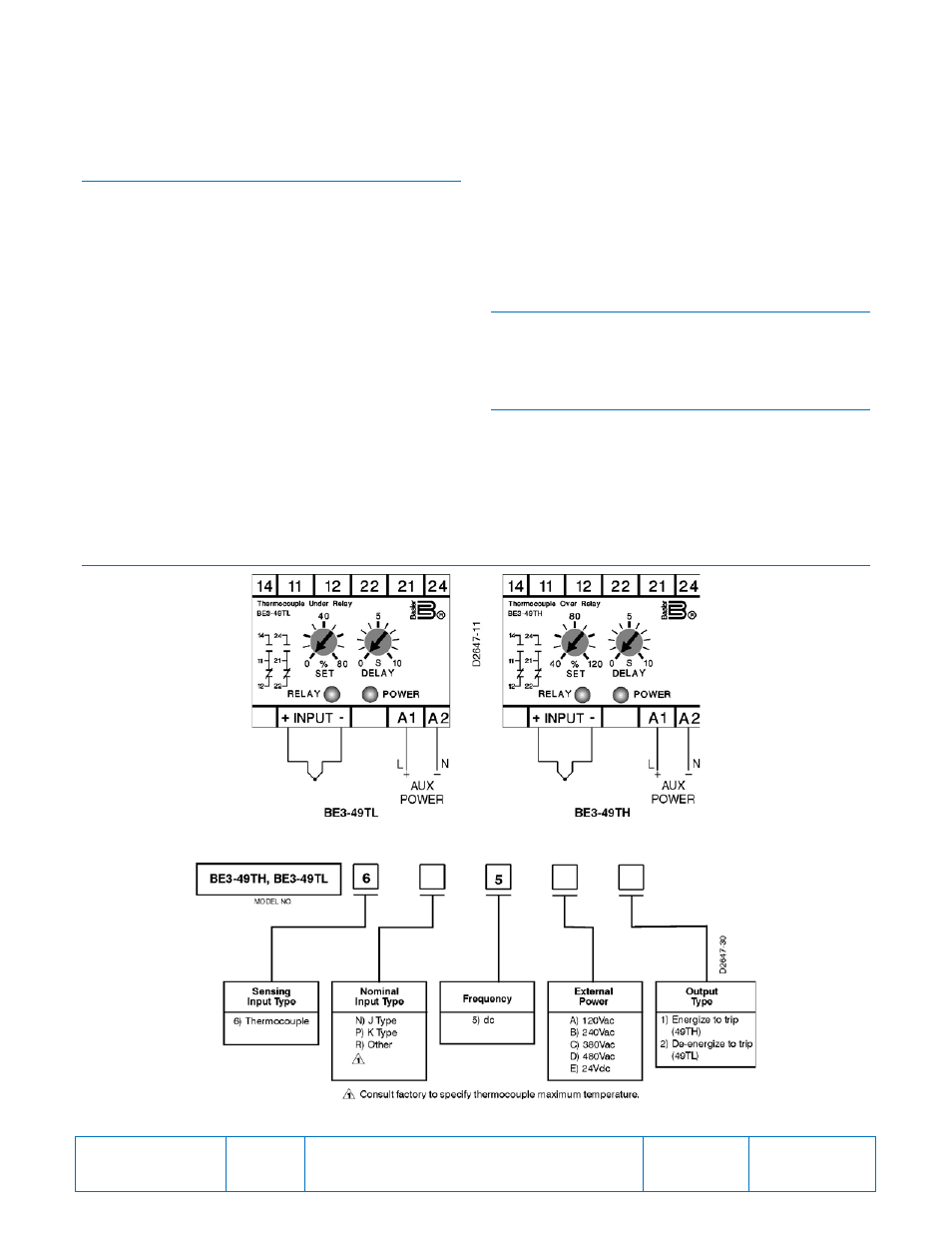
codes and is properly sized for the application. Figure 1
shows the terminal connections for the BE3-49TH and BE3-
49TL relays.
CALIBRATION
The calibration marks on the faceplate have a maximum
error of 10% and are provided only as guides. Proper
calibration requires using a thermocouple table and a
millivoltmeter connected in parallel with a stable low-voltage
source. Use the following procedure to calibrate your relay.
Trip
1.
Adjust the SET control fully clockwise (BE3-49TL) or
fully counterclockwise (BE3-49TH). Adjust the DELAY
control fully counterclockwise. Apply nominal external
operating power to the relay.
2.
Apply a value of millivolts that corresponds to the
desired temperature trip level.
3.
Slowly adjust the SET control until the relay trips.
Overtemperature Delay
1.
Set the DELAY control at the desired time setting. Apply
nominal external operating power to the relay.
2.
Apply a value of voltage that is just above the trip
setpoint. Measure the time from when the voltage is
applied until the relay trips.
3.
Compare the measured time delay to the desired time
delay and adjust the DELAY control accordingly.
4.
Repeat Steps 2 and 3 as required.
Undertemperature Delay
1.
Set the DELAY control at the desired time setting. Apply
nominal external operating power to the relay.
2.
Apply a value of voltage that is above the trip setpoint.
Remove the applied voltage and measure the time from
when the voltage is removed until the relay trips.
3.
Compare the measured time delay to the desired time
delay and adjust the DELAY control accordingly.
4.
Repeat Steps 2 and 3 as required.
MAINTENANCE
BE3 relays are solid-state devices that require no
maintenance. In the event that your relay requires repair,
contact Basler Electric, Highland, IL, USA for return
authorization.
ORDERING INFORMATION
Figure 2 shows the BE3 thermocouple temperature relay
style chart.
•
BE3-49TH - Overtemperature
•
BE3-49TL - Undertemperature
FIGURES
Figure 1. BE3-49TL and BE3-49TH Thermocouple Temperature Relay Connections
Figure 2. BE3-49TH and BE3-49TL Style Number Identification Chart
Publication
9320600990
Revision
E
Instructions
Date
03/14
Page
2 of 2