Instructions – Basler Electric BE3-74SH User Manual
Page 2
INSTALLATION
BE3 dc millivolt sensing relays are designed for mounting on
standard DIN rails that comply to DIN-EN 50022. Mounting
involves hooking the top edge of the cutout on the base of
the case over one edge of the DIN rail. The opposite side of
the cutout containing the release clip is then pushed over
the opposite side of the DIN rail. To remove or reposition the
relay, lever the release clip and move the relay as required.
BE3 relays should be installed in a dry, vibration-free
location where the ambient temperature does not exceed
the operating temperature range. Connections to the relay
should be made using wire that meets applicable codes and
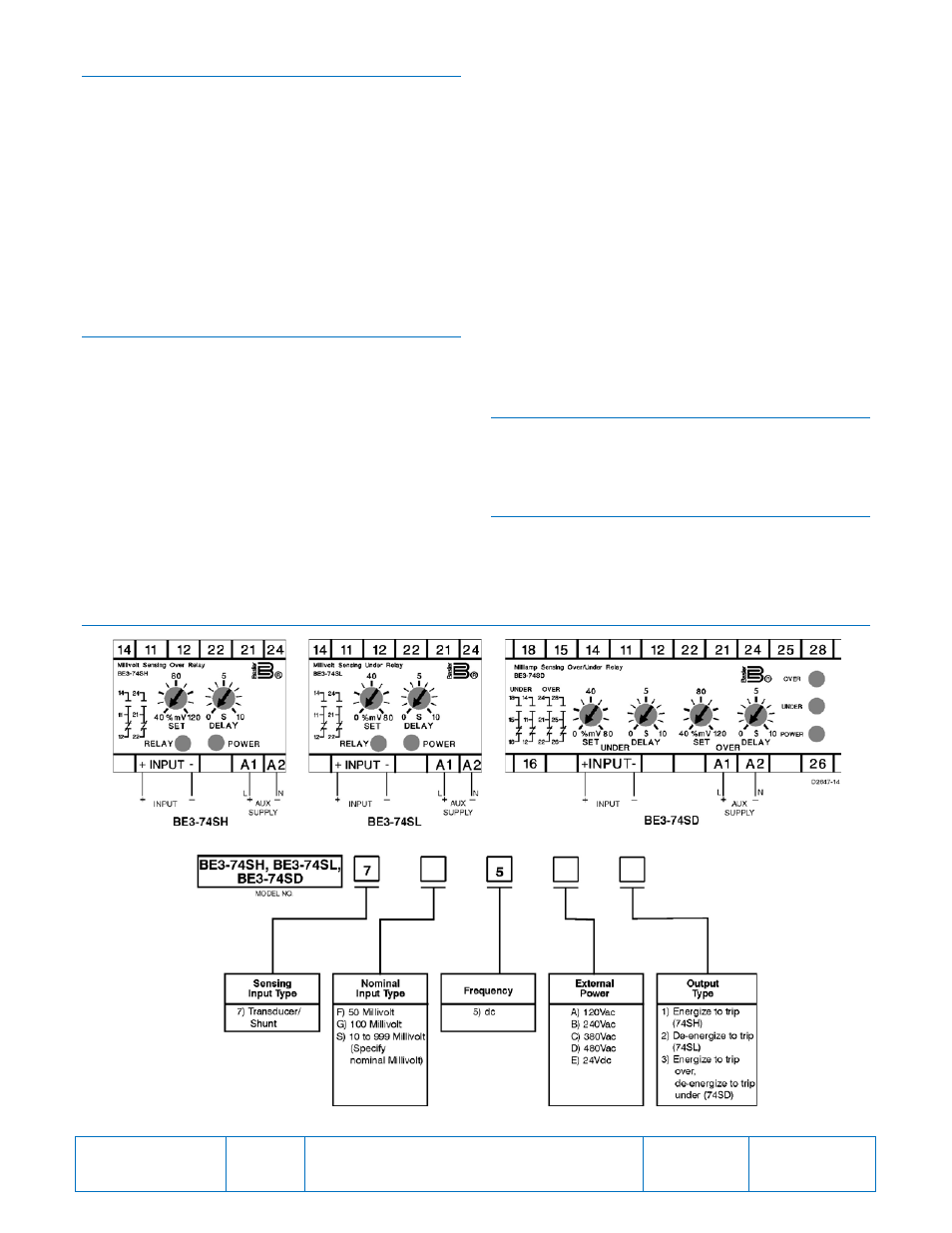
is properly sized for the application. Figure 1 shows the
input connections for the BE3-74SH, BE3-74SL, and BE3-
74SD relays.
CALIBRATION
The calibration marks on the faceplate have a maximum
error of 10% and are provided only as guides. Proper
calibration requires using an accurate millivolt meter in
parallel with the input signal. Use the following procedure to
calibrate your relay.
Overvoltage
1.
Adjust the SET control fully clockwise and the delay
control fully counterclockwise.
2.
Apply the desired trip voltage to the relay.
3.
Slowly (allow for the 200 ms operating time) adjust the
SET control counterclockwise until the relay trips.
4.
Remove the applied voltage (do not change the voltage
level) and set the DELAY control to the desired time
delay.
5.
Apply the trip voltage to the relay and measure the time
to trip.
6.
Adjust the DELAY and repeat Steps 4 and 5 until you
have the desired time delay.
Undervoltage
1.
Adjust the SET and DELAY controls fully
counterclockwise.
2.
Decrease the applied sensing voltage from the nominal
value until the desired tripping voltage is reached.
3.
Slowly (allow for the 200 ms operating time) adjust the
SET control clockwise until the relay trips.
4.
Set the DELAY control to the desired time delay and
apply nominal voltage to the relay.
5.
Step down the applied voltage from nominal to a level
just below the trip level set in Step 3 and measure the
time delay.
6.
Adjust the DELAY and repeat Steps 4 and 5 until the
desired time delay is achieved.
MAINTENANCE
BE3 relays are solid-state devices that require no
maintenance. In the event that your relay requires repair,
contact Basler Electric, Highland, IL, USA for return
authorization.
ORDERING INFORMATION
Figure 2 shows the BE3 relay style chart.
FIGURES
Figure 1. BE3-74SH, BE3-74SL, and BE-74SD Input Connections
Figure 2. BE3-74SH, BE3-74SL, and BE3-74SD Style Number Identification Chart
Publication
9320800990
Revision
C
Instructions
Date
03/14
Page
2 of 2