Instructions, Warning – Basler Electric ESD201 User Manual
Page 2
Publication
9110600991
Revision
F
Instructions
Date
09/12
Page
2 of 4
For terms of service relating to this product and software, see the Commercial Terms of Products and Services document available at
www.basler.com/terms
.
involves the use of the breaker auxiliary “a” contact. The
intent of the “a” contact is to inhibit operation of the
oscillator circuit (and thereby eliminate battery drain) until
the circuit breaker is closed.
Each breaker should be equipped with its own ESD 201.
The use of a single ESD 201 to provide a tripping output for
more than one breaker (or other device) is not
recommended. Such configurations should be considered
only when it can be demonstrated, through independent
testing, that combinations of breakers (or devices) can be
reliably operated from a single ESD 201.
OPERATION
When the ESD 201 is properly interconnected and 120 or
240 Vac input power is applied, the unit is ready for
operation. This can be verified by using the pushbutton as
described in the Controls and Indicators paragraph. No
adjustments of any type should be necessary.
AC power must be applied continually for a minimum of two
hours before the ESD 201 is capable of developing full
charge on the output capacitor with a sustained interruption
in ac input.
If the batteries are fully discharged (terminal voltage of 3.6
volts or less), it will take approximately 48 hours to
recharge the batteries from the ac source. In such
situations, it is suggested that the batteries be removed
and recharged with a high rate charger (not to exceed a
0.1-ampere charging rate). During this time, rechargeable
NiCd “AA” size cells (Basler Electric P/N 31129) should be
substituted in the ESD 201.
Note
Read the paragraphs under Discharging before
changing batteries.
DISCHARGING
Since more than 400 Vdc can be present on the ESD 201
output terminals, the storage capacitors should be
discharged before working on the unit. The following
procedure can be used for discharging the storage
capacitors.
Warning!
Lethal voltage may be present at ESD 201
terminals and within the ESD 201. Only qualified
persons should install, operate, or service this
device.
1.
Connect a few inches of 14 AWG, 600 V insulated wire
to each end of a 470
Ω, 5 W, wire-would resistor.
2.
Remove ac input power from ESD 201 terminals 1, 5,
and 2.
3.
To discharge the capacitors, carefully touch one of the
resistor wires to terminal 1 and the other wire to
terminal 3. Hold the wires on the terminals for at least
five seconds.
4.
Ensure that the capacitors are discharged by
connecting a dc voltmeter across terminals 3 (+) and 1
(
–).
STORAGE
This device contains long-life aluminum electrolytic
capacitors. For devices that are not in service (spares in
storage), the life of these capacitors can be maximized by
energizing the device for 30 minutes once per year.
REPAIRS
The ESD 201 is not field repairable. Should the device
require repairs, return it to Basler Electric for service.
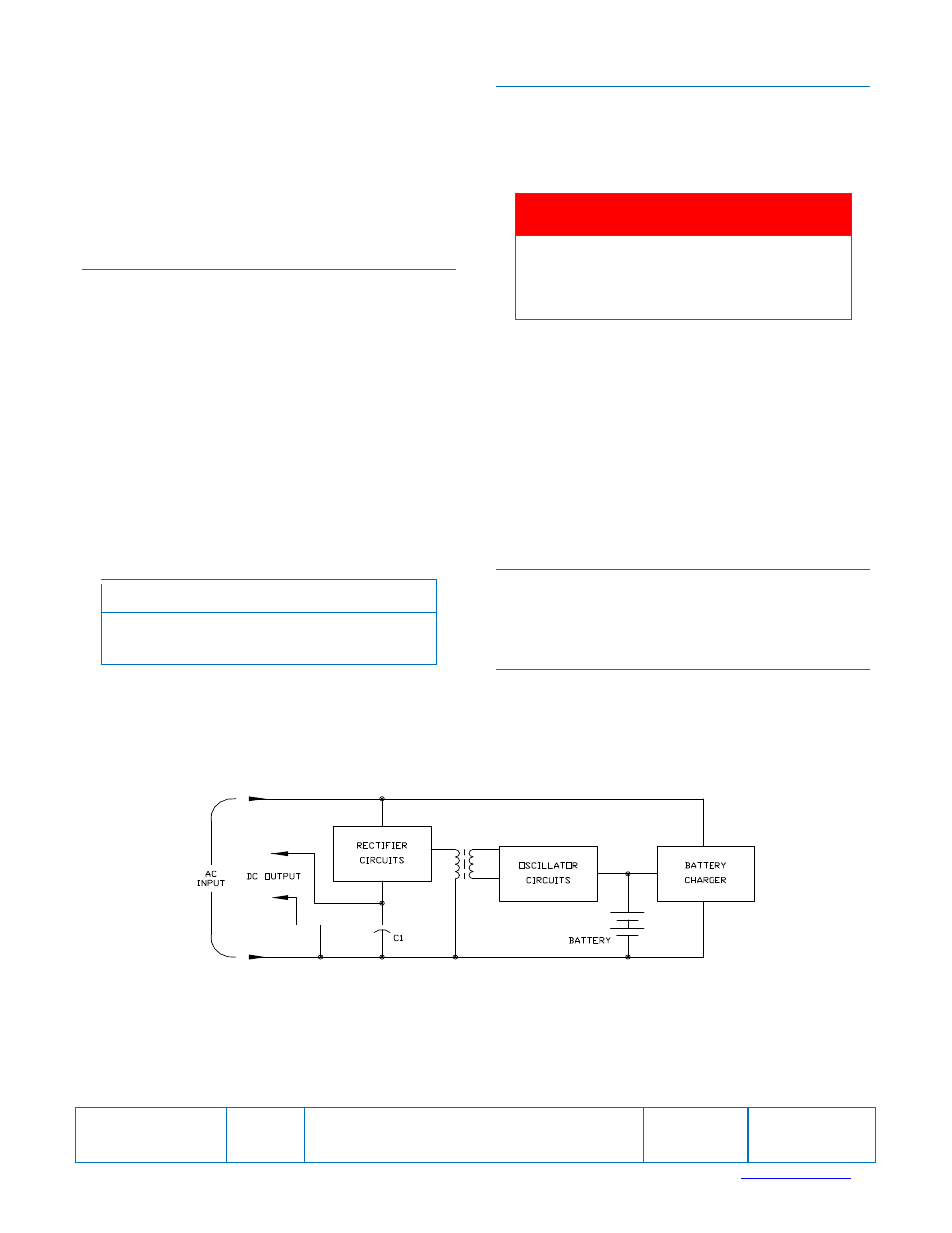
Figure 1. Function Block Diagram
D 2751-11