Leds for ip-link-bus-diagnosis – BECKHOFF CX1020 User Manual
Page 114
Error handling and diagnostics
112
Embedded PC
communication with Bus
Terminal n
9 pulses
0
Checksum error in Flash
program
Revert to the manufacturer’s setting
n (n>0)
Bus Terminal n is not
consistent with the
configuration that existed
when the boot project was
created
Revert to the manufacturer's setting which
will clear the boot project.
14 pulses
n
nth Bus Terminal has the
wrong format
Start the power supply again, and if the error
occurs again then exchange the Bus
Terminal.
15 pulses
n
Number of Bus Terminals is
no longer correct
Start the power supply up again.
16 pulses
n
Length of the K-Bus data is
no longer correct
Start the power supply up again.
Error code argument
The number of pulses indicates the position of the last Bus Terminal before the fault. Passive Bus Terminals, such as
a power feed terminal, are not included in the count.
In the case of some errors, rectification does not cause the power supply to leave the blink sequence. The power
supply can only be restarted by switching its supply voltage off and on again.
Note:
The supply voltage of the power supply unit, which is necessary to supply power to the CX-System, must not be
interrupted in the middle of operation. Switching off the supply voltage to the power supply unit refers here to the
power supply on the power contacts.
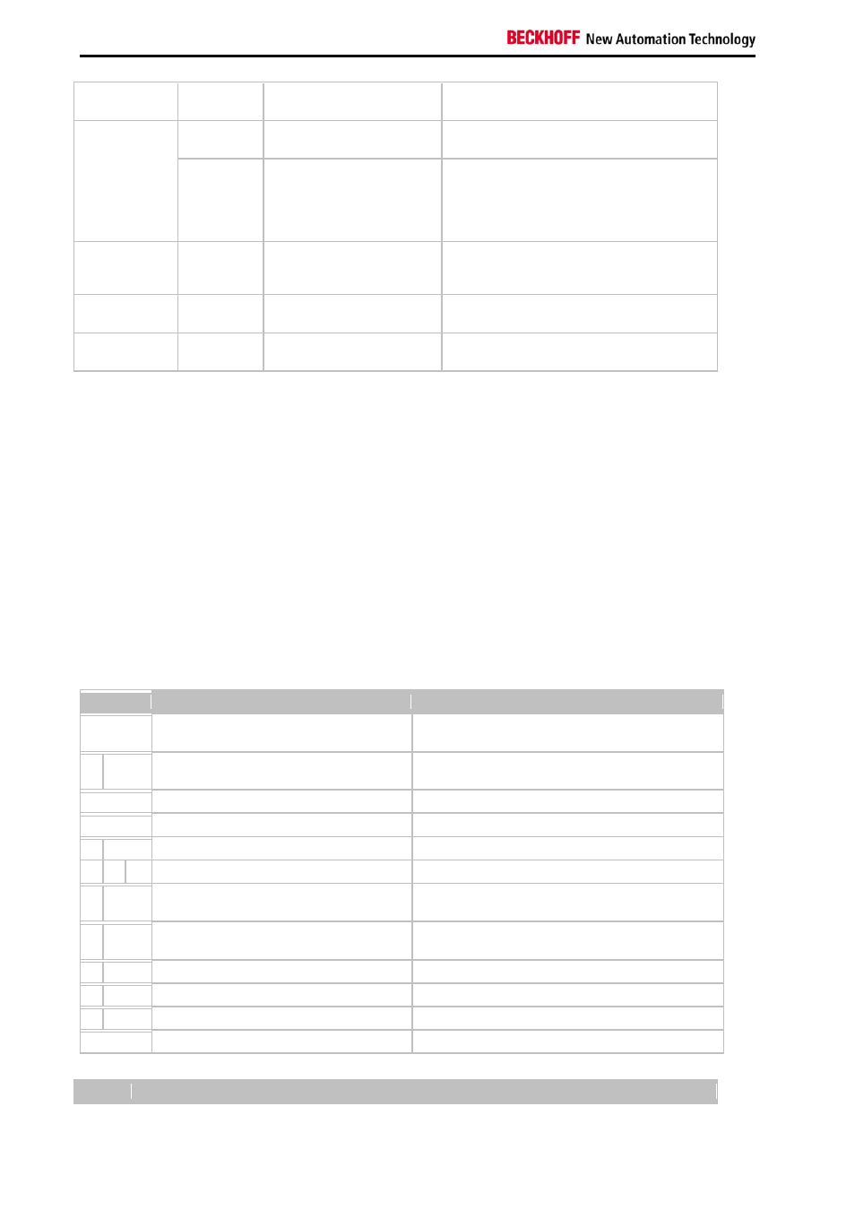
LEDs for IP-Link-Bus-Diagnosis
After a long flash (app.. 2 sec.) an IP-Link-Bus error has occurred. The following tables describe the error codes and
help to find the reason for the error. IP-Link errors most often turn out to be a result of inappropriate use of the optical
fiber.
I/O Err
Description
Remedy
off
No data exchange
Module in synchronous mode or - activate Profibus
cyclic data
1 0
EEPROM checksum error
Set manufacturer’s setting with the KS2000
software
2 Reserved
-
3
Break location has been recognized
interruption before the master's receiver
3 n
Break location has been recognized
n-th module before the master's receiver
3 n m Break location has been recognized
(n*10)+m-th module before the master's receiver
4 n
Too many faulty telegrams have been
detected (more than 25%)
The optical fiber wiring in front of the nth extension
module should be checked
5 n
Register access to complex modules has
failed
Check the nth module
11 n
Complex module working incorrectly
Exchange the nth module
12 n
More than 120 modules in the ring
Connect fewer modules
13 n
nth module unknown
Firmware update required
off
Module is exchanging data
no error
Note