BECKHOFF ZS1020-0010 User Manual
Montagehinweise ip-link-stecker, Mounting instructions ip-link connector, Instructions de montage connecteur ip-link
Montagehinweise
IP-Link-Stecker
Verlegehinweise
Den Lichtleiter bei der Montage nicht knicken!
Der Biegeradius des Lichtwellenleiters beträgt
min. 50 mm. Engere Biegeradien können den
Leiter beschädigen.
Mounting instructions
IP-Link connector
Fibre optic installation
The fibre optic may not be bent during mounting!
The minimum bending radius of the fibre optic
is 50 mm. Bending radiuses below 50 mm can
damage the fibre optic.
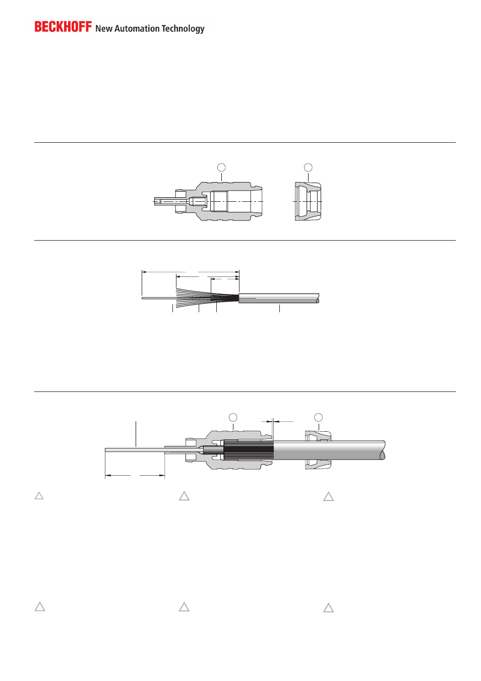
Fig. 1:
Steckerteile Übersicht
Fig. 2: Lichtwellenleiter vorbereiten
A: Außenmantel
K: Kevlar-Faser
U: LWL-Ummantelung
L: Lichtwellenleiter
Leitungsende nach Fig. 2 abmanteln!
A: Outer sheat
K: Kevlar fibre
U: Fibre coating
L: Fibre optic
Strip cable end according to Fig. 2!
Fig. 3: Montage des Steckers
( a ) Leitungsmantel nach Fig. 2 abmanteln
Achtung: Abisolierzange verwenden!
( b ) Teil
über den orangefarbenen
Außenmantel ziehen
( c ) Gelbe Kevlar-Faser über den Außenmantel
zurücklegen
( d ) Teil
auf den Außenmantel stecken. Der Stecker
muss durch Drehen im Uhrzeigersinn so lange von
Hand aufgeschraubt werden bis er spürbar fest
ist. Dazu sind mindestens 4 Umdrehungen not
wendig.
DerKunststoffkörper des Steckers ist so konzipiert,
dass er in die LWL-Ummantelung U ein Gewinde
schneidet.
Achtung: Keine Werkzeuge verwenden!
Nicht überdrehen!
Fortsetzung auf Rückseite
Fig. 1: Connector parts
Fig. 2:
Preparing the fibre optic
Fig. 3: Assembling the connector
Fig. 3:
Montage du connecteur
( a ) Strip cable end according to Fig. 2
Attention: Use insulation stripper!
( b ) Pull part
over the orange outer sheath
( c ) Bend yellow Kevlar fibre back over the
outer sheath
( d ) Plug part
onto the outer sheath.
Hand screw the connector clockwise, at least 4
turns, onto the cable until tight.
Due to its specific design, the plastic connector
body automatically cuts a thread into the fibre’s
coating U.
Attention: Do not use any tools!
Do not overtighten!
continued overleaf
Instructions de montage
Connecteur IP-Link
Montage de la fibre optique
Ne pas plier la fibre optique lors du montage! Le
rayon de courbure de la fibre optique est de min.
50 mm. Des rayons de courbures en-dessous de
50 mm peuvent endommager la fibre.
A: gaine extérieure
K: fibre Kevlar
U: enrobage fibre optique
L: fibre optique
Dénuder l‘extrémité du câble suivant
Fig. 2!
Fig. 1: Aperçu des composants du
connecteur
Fig. 2: Préparation de la fibre
optique
( a ) Dénuder l‘extrémité du câble suivant Fig. 2
Attention: utiliser une pince à dénuder!
( b ) Glisser la partie
sur la gaine extérieure
orange
( c ) Replier la fibre jaune Kevlar sur la gaine
extérieure
( d ) Glisser la partie
sur la gaine extérieure. La
partie plastique du connecteur est conçue de telle
manière qu‘elle coupe un filetage dans l‘enrobage
de la fibre optique U. Visser à la main le connec-
teur dans le sens des aiguilles de montre jusqu‘à
la butée.
Attention: Ne pas utiliser des outils!
Ne pas fausser !
Voir la suite à la page suivante
2
1
8
2
L
1
<1mm
23
6
L
K
U
A
19
!
!
!
!
!
!