15 ide interface, Aution – BECKHOFF CB3052 User Manual
Page 31
IDE Interface
Chapter: Connectors
Beckhoff New Automation Technology CB3052
page 31
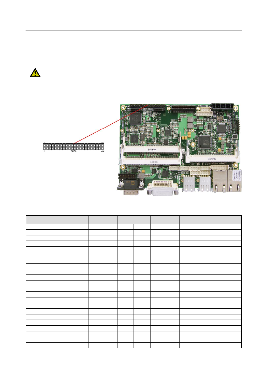
3.15 IDE Interface
The primary IDE interface is a standard IDC socket connector with a spacing of 2 mm. All commercial IDE
devices are supported but an adapter to connect may be necessary.
The required settings are made in the BIOS setup.
C
AUTION
Pins are not keyed! Please be sure to connect the cable properly, otherwise you risk damaging the IDE
interface, the CPU and the drive, voiding respective warranties.
Pinout for primary IDE
Description
Name
Pin
Name
Description
reset
PRST#
1
2
GND
ground
data bit 7
PDD7
3
4
PDD8
data bit 8
data bit 6
PDD6
5
6
PDD9
data bit 9
data bit 5
PDD5
7
8
PDD10
data bit 10
data bit 4
PDD4
9
10
PDD11
data bit 11
data bit 3
PDD3
11
12
PDD12
data bit 12
data bit 2
PDD2
13
14
PDD13
data bit 13
data bit 1
PDD1
15
16
PDD14
data bit 14
data bit 0
PDD0
17
18
PDD15
data bit 15
ground
GND
19
20
N/C
reserved
DMA request signal
PDDREQ
21
22
GND
ground
write signal
PDIOW#
23
24
GND
ground
read signal
PDIOR#
25
26
GND
ground
ready signal
PDRDY
27
28
N/C
reserved
DMA acknowledge signal
PDDACK#
29
30
GND
ground
interrupt signal
PDIRQ
31
32
N/C
reserved
address bit 1
PDA1
33
34
PDMA66EN enable UDMA66
address bit 0
PDA0
35
36
PDA2
address bit 2
chip select signal 0
PDSC0#
37
38
PDCS1#
chip select signal 1
reserved
N/C
39
40
GND
ground
supply HDD 5V
VCC
41
42
VCC
supply HDD 5V
ground
GND
43
44
N/C
reserved