1 connector map – BECKHOFF CB4052 User Manual
Page 14
Chapter: Connectors
Connector Map
page 14
Beckhoff New Automation Technology CB4052
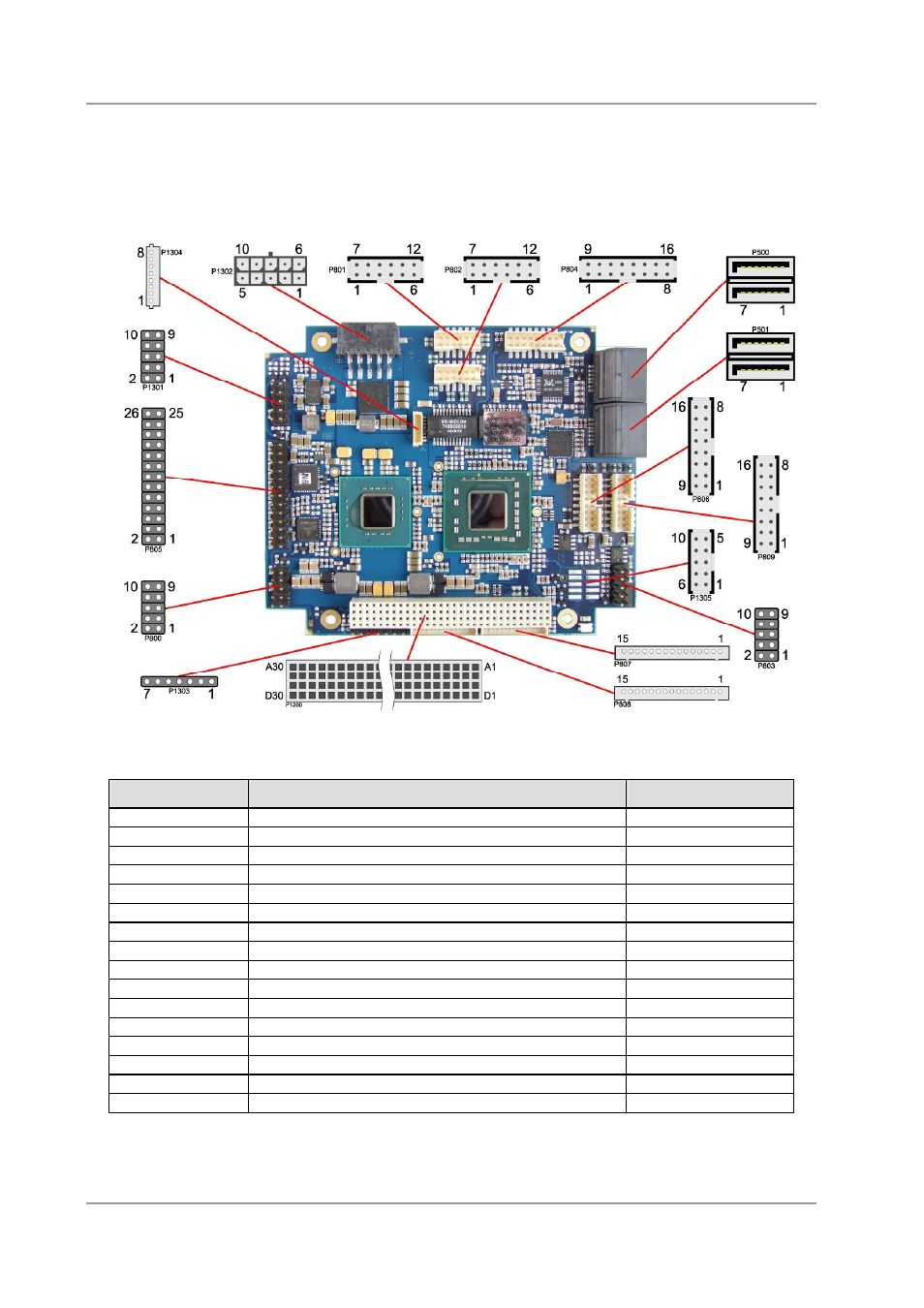
3.1 Connector Map
Please use the connector map below for quick reference. Only connectors on the component side are
shown. For more information on each connector refer to the table below.
Ref-No.
Function
Page
P500/P501
"SATA Interfaces"
p. 30
U600*
"Memory"
p. 17
P800
"Serial Interface COM1"
p. 32
P801/P802
"LAN"
p. 28
P803
"Serial Interface COM2"
p. 33
P804
"Audio"
p. 29
P805
"Parallel Interface LPT"
p. 31
P806/P809
"USB"
p. 27
P807/P808
"LCD"
p. 25
P1200*
"PCI/104-Express Bus"
p. 22
P1300
"PC/104-Plus Bus"
p. 20
P1301
"System"
p. 16
P1302
"Power Supply"
p. 15
P1303
"SMBus"
p. 34
P1304
"Monitoring Functions"
p. 35
P1305
"VGA"
p. 24
* not in the picture above (cf. bottom side of board)