Exploded view of connector parts, Prepare cable ends, Pre-assemble cable grip – BECKHOFF II/O-Lightbus User Manual
Page 7: Assemble guide pin, Abrade fiber to final dimension
Eiserstr. 5, D-33415 Verl, Germany, Phone +495246/963-0, Fax +495246/963-149
Optical fibre installation instructions
6
II/O-Lightbus
Assembly instructions for the IP65 circular
connector Z1002
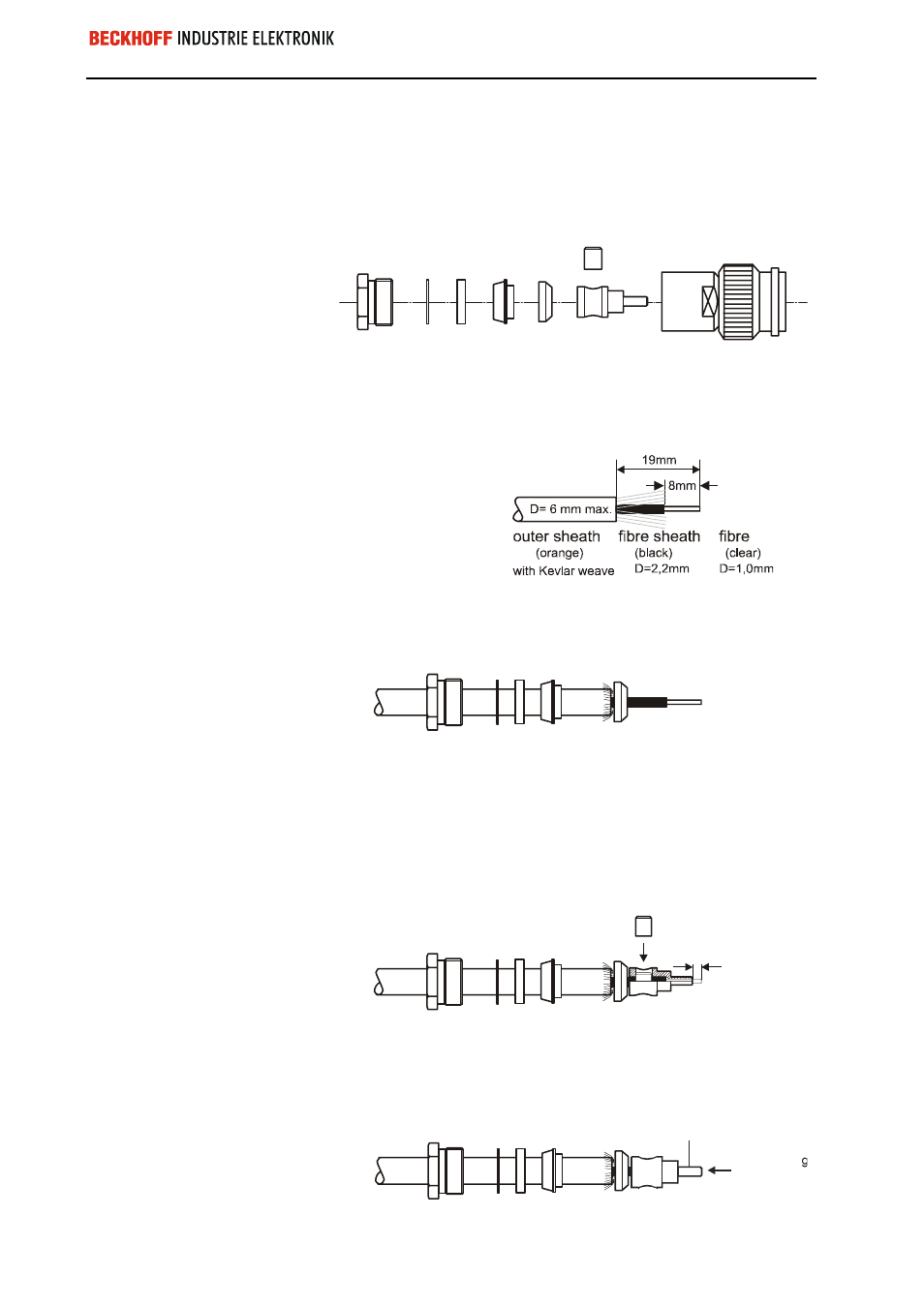
Exploded view of connector parts
Individual parts
screw fitting
seal ring
cutting ring
guide pin
connector body
washer
clamping
washer
clip
1. Prepare cable ends
Do not kink light guide!
(bending radius min.
30mm)
Do not damage the fiber!
(increased cable
attenuation)
First remove the orange outer sheath to approx. 19 mm.
Remove the Kevlar weave and the black fiber sheath to approx. 8 mm. The
fiber must not be damaged during this process.
2. Pre-assemble cable grip
Push screw fitting, washer, seal ring and cutting ring over the outer sheath.
Push clamping washer over the fiber sheath.
3. Assemble guide pin
The fiber must initially
project by approx. 2 mm!
Position the guide pin on the optical fiber up to the stop. The fiber must
project from the connector guide by approx. 2 mm, so that any cracks
present in the fiber end face are located outside the connector (these are
subsequently removed by abrasion).
To secure the connector guide insert the clip into the connector body and
press in without canting. Note clip – groove alignment!
clip
~2mm
4. Abrade fiber to final dimension
Abrade the fiber flush with
the guide pin!
Do not cut off the projecting fiber end (this could lead to crack formation)
but abrade flush with the connector guide using abrasive paper (600 grain
size). The connector guide must not be abraded during this process.
Connector guide
Abrade
fibre flush