Besa Lighting Pogo (Mini Pendants 12V) User Manual
Fixture installation guide
FIXTURE INSTALLATION GUIDE
All electrical connections and the installation of this fixture must be in agreement with local codes,
ordinances or the NEC (National Electric Code) or CEC (Canadian Electrical Code).
Do not connect this fixture to an electrical system that does not provide a means for equipment grounding.
Model T21T (Low Voltage Pendant Set 120V)
21T, Rev.4 6-13
IMPORTANT: Before proceeding, retrieve the GLASS SHADE INSTALLATION GUIDE,
which is included with the pendant cord set
CAUTION: Turn off power to electrical box before installing
6695 Taylor Rd. Blacklick, OH 43004
www.besalighting.com
C
D
E
F
G
1. Carefully unpack parts. Remove the Canopy (A) from the Mounting Plate by unscrewing the Retainer (B).
Fully remove the Retainer from the threaded nipple, then pull the canopy from the Mounting Plate.
IMPORTANT:
Refer to the
GLASS SHADE INSTALLATION GUIDE to determine the glass support
parts that must be installed over the Pendant Cord Set, prior to Step 2.
2. To install the pendant cord, simply unscrew the Set Screw on the Strain Relief (C) to loosen.
Now push the cord up through the Retainer, Canopy and then Strain Relief until reaching the
desired length. Shorten cord to approx. 6” above the Strain Relief, per instructions on the Glass
Installation Guide. Tighten the Set Screw onto cord until the cord is held in place.
CAUTION: Overtightening the set screw could pierce cord and prevent pendant from operating.
3. Connect the cord leads to the blue or red transformer wires, and secure with wirenuts (D).
If the cord length above the Mounting Plate is more than 6”, then you will need to shorten the cord.
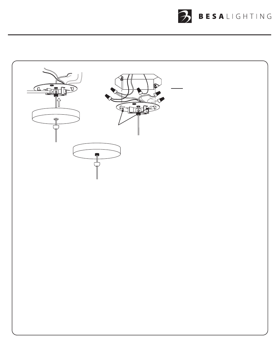
4. Install the provided Mounting Screws into the Outlet Box, leaving 1/4” of threading as shown.
Attach the house ground wire to the bare copper lead on the Mounting Plate and secure with
provided wirenut (E). Connect the electrical leads from the fixture transformer to the house
supply wires, black to black, white to white, and secure with wirenuts provided (F).
5. Align the circular openings of the keyhole slots (G) of the Mounting Plate with the Mounting screws.
Push the Mounting Plate up over the Outlet Box until tight to ceiling, then rotate the Mounting Plate
Counter-clockwise and secure with Mounting Screws.
6. Position canopy over the threaded nipple and secure with Retainer.
7. For assembly of the glass shade, please refer to the
GLASS SHADE INSTALLATION GUIDE
that is included with the Pendant Cord Set.
8. Restore power.
A
B
*IMPORTANT:
When Mounting To Smaller Boxes,
It May Be Necessary To Secure
Using These Mounting Holes.
Note:
For optimum performance,
an electronic low voltage dimmer
should be used. Installation of a
low voltage dimmer requires a
neutral lead in the switch box for
proper wiring.
If employing a standard incandescent
dimmer, low levels of noise (”buzzing”)
may emanate from either the dimmer or
transformer. This is usually caused by
dimmer/transformer incompatibility and
may be eliminated by simply replacing
the dimmer.
Flat Monopoint (12V Quick Connect Canopies), Botella (Mini Pendants 12V), Kiki (Mini Pendants 12V), Zumi (Mini Pendants 12V), Juliette (Mini Pendants 12V), Scope (Mini Pendants 12V), Pahu 4 (Mini Pendants 12V), Focus (Mini Pendants 12V), Kani (Mini Pendants 12V), Kona (Mini Pendants 12V), Trilo 7 (Mini Pendants 12V), Brella (Mini Pendants 12V), Domi (Mini Pendants 12V), Spazio (Mini Pendants 12V), Nico 4 (Mini Pendants 12V), Tay Tay (Mini Pendants 12V), Hoppi (Mini Pendants 12V), Divi (Mini Pendants 12V), Pera 6 (Mini Pendants 12V), Camino (Mini Pendants 12V), Amelia 6 (Mini Pendants 12V), Stilo 7 (Mini Pendants 12V), Copa (Mini Pendants 12V), Tu tu (Mini Pendants 12V), Karli (Mini Pendants 12V), Groove (Mini Pendants 12V), Sasha (Mini Pendants 12V), Sprite (Mini Pendants 12V)
Document Outline
- 21T,rev4
- UKIT.91_Rev1
- UKIT.91_Rev1
- UKIT.91_Rev1
- UKIT
- UKIT.91_Rev1_BACK
- UKIT
- UKIT.91_Rev1
- UKIT.91 back
- UKIT.91_Rev1
- 21QP,rev3 (Target)
- XPKIT.91_Rev1
- XPKIT.91_Rev1
- XPKIT.91_Rev1
- XPKIT
- UKIT.91_Rev1_BACK
- UKIT
- XPKIT.91_Rev1
- UKIT.91 back
- XPKIT.91_Rev1