Besa Lighting Brella (Linear Pendants) User Manual
Installation guide, Side view
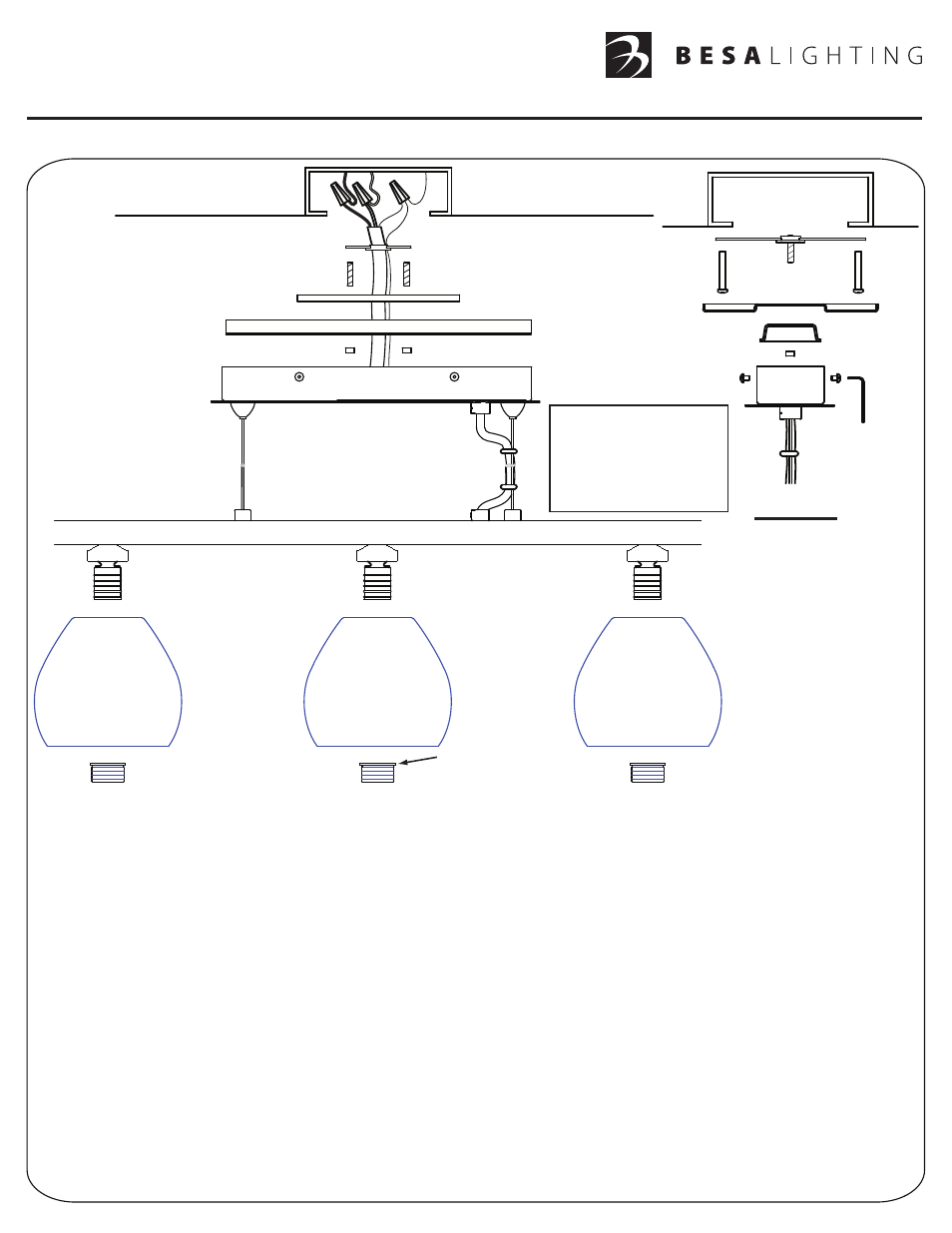
INSTALLATION GUIDE
Model LP Series (Multi-Light G9 Pendant 120V)
LP, Rev.3 9-11
Caution: Turn off power to electrical box before installing
6695 Taylor Rd. Blacklick, OH 43004
www.besalighting.com
1. Carefully unpack parts. Using the Allen Wrench provided, loosen Screws (F) to release the Fixture Mounting Plate (A) from Canopy (G).
2. Determine the overall length of cord and cable desired, then adjust using the Cable Grips (N) and Cord Strain Relief (P). To adjust cable
length, push the cable up through the Cable Grip. To increase the cable length, push the Cable Grip upwards and the cable will be released
for lowering. Run the cord through the center openings on Fixture Mounting Plate (A), Decorative Cover (H) and Mounting Bracket (B).
If using 18” Decorative Cord Sleeve(s), cut to desired length and slide onto cord prior to running the cord through the center openings. The
Decorative Cord Sleeve(s) will then be secured by pulling the cord through the Cord Strain Relief and tightening the set screw.
3. Attach the bare copper fixture ground wire and bare ground conductor from the cord to the supply ground and secure with Wire Nut
Connector (D).
4. Connect the cord conductors to the supply conductors with Wire Nut Connectors (E) as shown: Cord conductor with white stripe to white
supply wire and clear cord conductor to black supply wire. Carefully push wires and wire nuts back into outlet box.
5. Secure the Mounting Bracket (B) to the Electrical Supply Box with Machine Screws (C) provided. (See Side View).
6. After securing the Threaded Posts (I) into the holes in the shorter section of the Mounting Bracket (B), align the circular openings on the
Decorative Cover (H) and Fixture Mounting Plate (A) with the Threaded Posts on the Mounting Bracket. Push the Decorative Cover and
Fixture Mounting Plate over the Threaded Posts until the Decorative Cover is flush with the ceiling, then secure with the Cap Nuts (J).
7. Position the Canopy (G) over the Fixture Mounting Plate (A) and secure by tightening the Screws (F) with the Allen Wrench provided.
(See Side View).
8.
Install the Glass Shade (L) by positioning the Socket (K) through the opening in the Glass Shade and secure using the Threaded
Adapter (M) insuring the wider section of the Threaded Adapter is towards the inside of the Glass Shade.
A
F
E
B
D
G
J
G
A
SIDE VIEW
I
J
I
H
K
L
M
Wider Section
H
C
C
I
B
F
F
J
N
P
N
Note that the cables may
retain memory from being
coiled. Simply remove from
Cable Grip, allow cables to
loosen, then reinstall into
Cable Grip.