Besa Lighting Moto (Metalworks) User Manual
Fixture installation guide
FIXTURE INSTALLATION GUIDE
All electrical connections and the installation of this fixture must be in agreement with local codes,
ordinances or the NEC (National Electric Code) or CEC (Canadian Electrical Code).
Do not connect this fixture to an electrical system that does not provide a means for equipment grounding.
Models 104, 105, 106, 107, 108, 109, 111, 112, 113
(Incandescent Stainless Steel Outdoor Wall Sconce 120V)
MOTO SCONCE, Rev.5 10-10
CAUTION: Turn off power to electrical box before installing
CAUTION--RISK OF FIRE: Min 75C SUPPLY CONDUCTORS. This fixture requires that the branch
supply wires be rated: MIN 75C. Most dwellings built before 1985 have supply wire rated 60C.
CONSULT A QUALIFIED ELECTRICIAN TO ENSURE CORRECT BRANCH CIRCUIT CONDUCTOR.
6695 Taylor Rd. Blacklick, OH 43004
www.besalighting.com
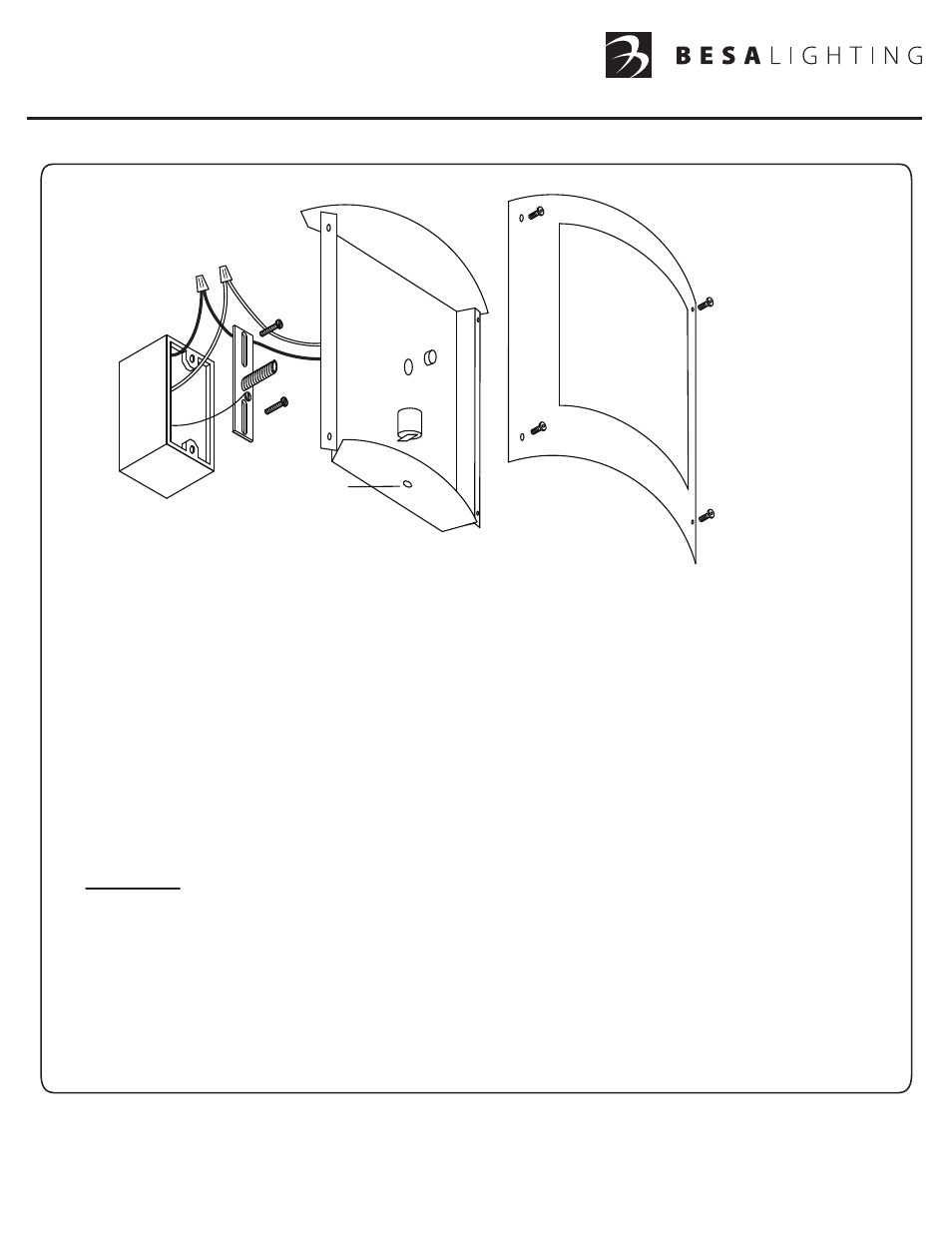
1. Carefully remove parts from package.
2. Attach the Mounting Bracket (A) to the Outlet Box with two Machine Screws (B) (not provided).
3. Thread the Threaded Nipple (C) into the center of the Mounting Bracket.
4. Connect the House Ground Wire to the Green Ground Screw on the Mounting Bracket (E).
5. The Faceplate (H) must be removed prior to mounting to wall. Remove the four Allen Head Screws (I) from the
Faceplate, then carefully pull from the Backplate. Lay Faceplate face down on a surface that will not scratch. The
four Allen Head Screws will be needed to reattach the Faceplate.
6. Connect the electrical leads from the fixture to the house supply wires, black to black and white to white, and secure
with wirenuts (D) (not provided). Push the excess wiring into the Outlet Box.
7. With the Backplate
oriented with the drainhole down, align the circular opening on the Backplate with the Threaded
Nipple (C) on the Mounting Bracket. Push the Backplate over the Threaded Nipple until the Backplate is flush with
the wall, then secure with the Cap Nut (F).
8.
IMPORTANT: IN ORDER TO COMPLY WITH ESTABLISHED ELECTRICAL CODE, THE INSTALLER MUST SEAL
THE AREA AROUND THE FIXTURE CANOPY, BETWEEN THE CANOPY AND THE WALL WITH A TYPE OF
CAULKING COMPOUND SUCH AS SILICONE RUBBER TO PROVIDE A WATERTIGHT SEAL IN ACCORDANCE
WITH THE DIFFERING SURFACE TEXTURES OF THE WALL.
9. With the power still off, insert bulb(s) of not more than the labeled wattage.
10. Prior to installing Faceplate (H), position the Faceplate so that the label on the backside is at the bottom. Place the
Faceplate (H) over the Backplate, aligning the backplate holes (G) and the slotted holes on the Faceplate. Secure
the Faceplate with the four Allen Head Screws.
DO NOT OVERTIGHTEN.
11. Restore Power.
A
B
C
D
E
F
G
NOTE:
Faceplate shown is
for example purposes,
the actual Faceplate
may be different
in appearance.
H
I
Drainhole down