Besa Lighting Bree (Metalworks) User Manual
Fixture installation guide
FIXTURE INSTALLATION GUIDE
All electrical connections and the installation of this fixture must be in agreement with local codes,
ordinances or the NEC (National Electric Code) or CEC (Canadian Electrical Code).
Do not connect this fixture to an electrical system that does not provide a means for equipment grounding.
Models Scala, Napoli, Bree (Incandescent Outdoor Wall Sconce 120V)
SCALA, NAPOLI, BREE_Glass, Rev.1 6-13
CAUTION: Turn off power to electrical box before installing
6695 Taylor Rd. Blacklick, OH 43004
www.besalighting.com
1. Carefully remove parts from package.
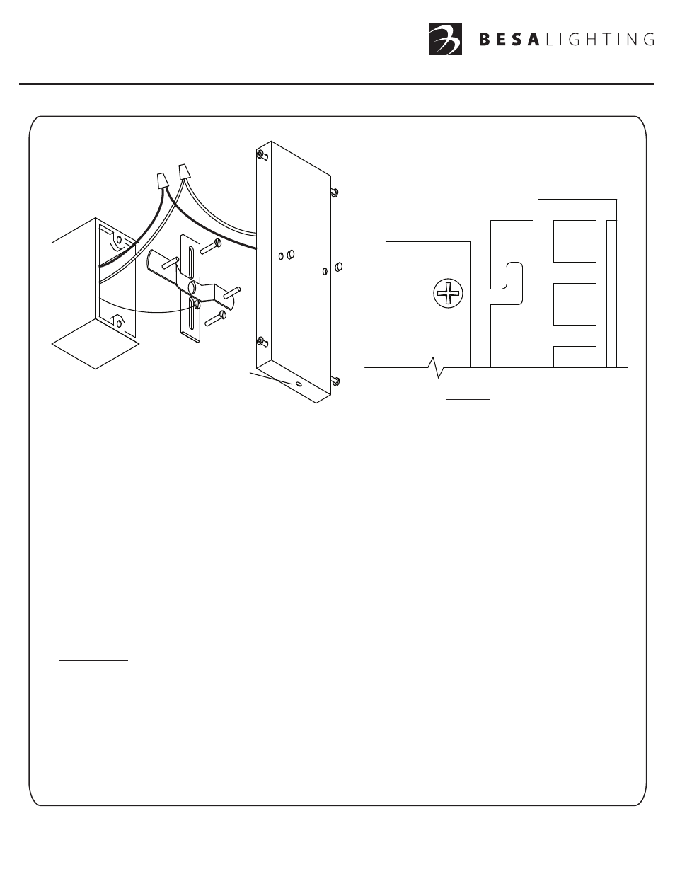
2. Attach the Mounting Bracket (A) to the Outlet Box with two Machine Screws (B).
3. Thread the two Threaded Posts (C) into the inner holes on the Mounting Bracket.
Rotate the Mounting Bracket so the Posts are oriented as shown.
4. Connect the House Ground Wire to the Green Ground Screw on the Mounting Bracket (E).
5. Remove the Glass/Metal Frame (I) assembly from the Backplate (F) by loosening the four retaining screws (H) and
then unhooking the neck of the frame fully from the canopy (see Fig. A).
6. Connect the electrical leads from the fixture to the house supply wires, black to black and white to white, and secure
with wirenuts provided (D). Push the excess wiring into the Outlet Box.
7. With the Backplate (F) oriented with the drainhole down, align the circular opening on the Backplate with the Threaded
Posts (C) on the Mounting Bracket. Push the Backplate over the Threaded Posts until the Backplate is flush with
the wall, then secure with the Cap Nuts (G).
8.
IMPORTANT: IN ORDER TO COMPLY WITH ESTABLISHED ELECTRICAL CODE, THE INSTALLER MUST SEAL
THE AREA AROUND THE FIXTURE BACKPLATE, BETWEEN THE BACKPLATE AND THE WALL WITH A TYPE OF
CAULKING COMPOUND SUCH AS SILICONE RUBBER TO PROVIDE A WATERTIGHT SEAL IN ACCORDANCE
WITH THE DIFFERING SURFACE TEXTURES OF THE WALL.
9. With the power still off, insert bulb(s) of not more than the labeled wattage.
10. Place the Glass/Metal Frame unit onto the previously installed Backplate (F). Hook the neck of the frame fully onto the
backplate (see Fig. A). Tighten the four retaining screws (H) .
11. Restore Power.
Note: Box shown is for
instructional purposes only.
Actual box size may vary.
A
B
C
D
E
F
G
H
H
H
GLASS/METAL FRAME
BACKPLATE (F)
Fig. A
I
G
Drainhole down