0 control operations – BSS Audio OPAL Series DPR-522 Owner's Manual User Manual
Page 13
13
6.0
Control Operations
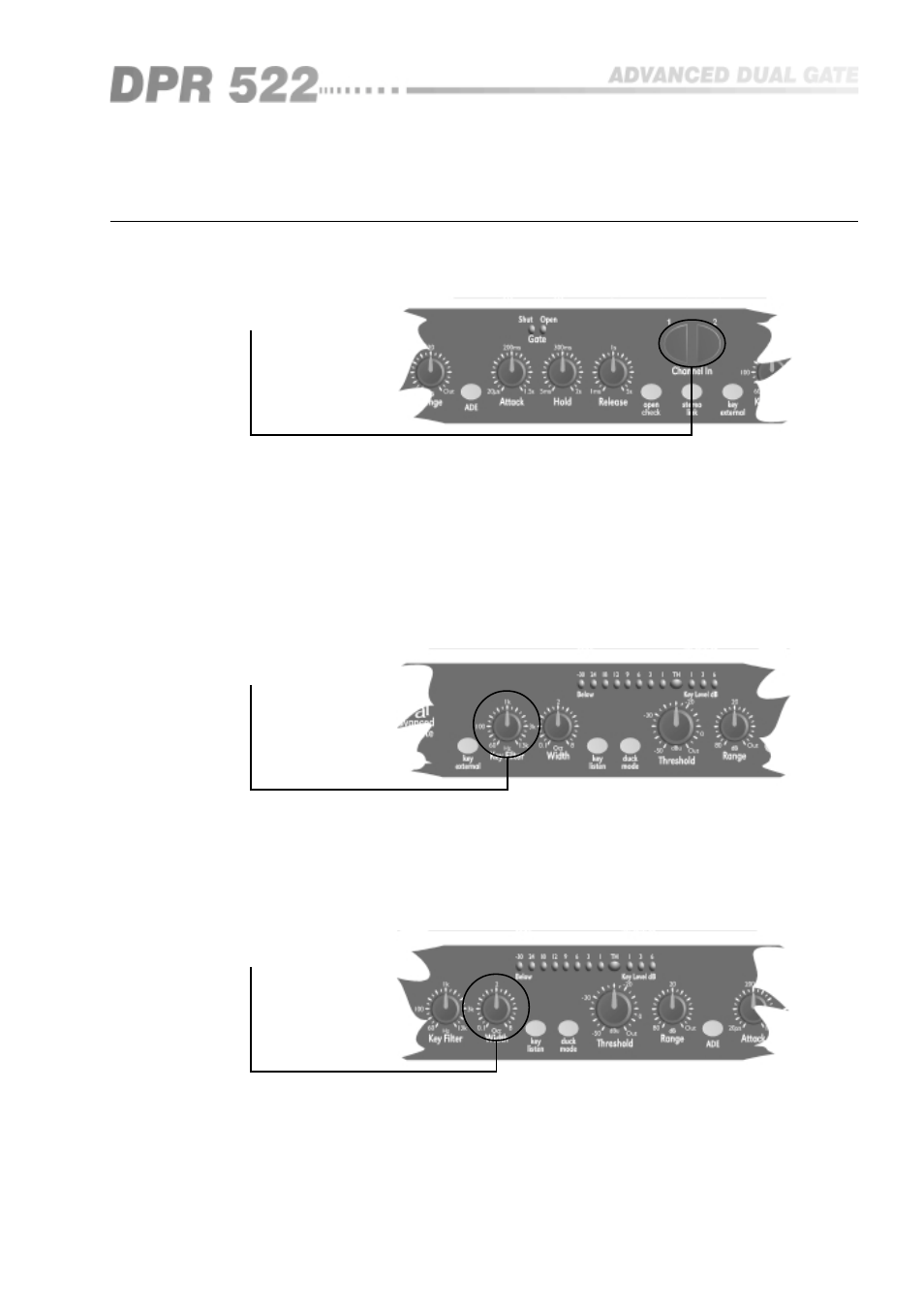
6.1 Channel In
When the CHANNEL IN switch is in the out, non illuminated position, all
DPR-522 functions are bypassed and the input is connected directly to the
output with a high quality relay. This is the same condition that occurs when
the power is off, and ensures that signal is passed through the unit in the case
of a power or fuse failure. When the switch is pushed, the processed signal is
present on the output.
In bypass mode, the input is still connected to all of the DPR-522 circuitry, so
that all of the required facilities can be selected and set up prior to operating
the CHANNEL switch and going ‘on-air’.
6.2 Key filter
This control adjusts the centre frequency of the internal key parametric filter.
This filter is used to control the frequency content of the signal being sent to
the gate control circuitry to allow the filtering out of signals not required to
control the gating action. The filter is not placed in the main signal path, and
therefore has no effect whatsoever on the program material passing through
the gate.
6.3 Width
This control adjusts the width of the internal key filter. This filter should be
considered as a pair of tracking high pass and low pass filters, with the space
between them controlled by the WIDTH control. It is thus possible to achieve
a variety of key filter responses, from a very broad filter encompassing the
entire audio band to a very narrow one for a very selective response.
Normally it is best to start off with a fairly wide setting and then narrow down
on the signal of interest, readjusting the KEY FILTER control if required.
Control operations