Electrical component chart – BUG-O Systems CW-11 User Manual
Page 28
28
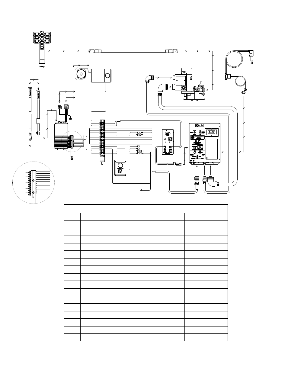
ELECTRICAL COMPONENT CHART
ITEM DESCRIPTION
PART NO.
1
LN-9 Wire Feeder
BUG-3291
2
Weld Cable 4/0 50'
CWO-3040
3
Collector w/Power Racker
CWO-3133
4
Brush Holder & Support w/ Power Racking
CWO-3315
5
4006 Motor Assembly
CWO-3506
6
LN-9 Wire Feeder Control
CWO-3535
7
Brush Retainer w/Power Racking
CWO-3931
8
Terminal Block Assembly
CWO-3969
9
Weld Cable 4/0
CWO-3970
10
4/0 Weld Cable Inlet
CWO-3020-4/0
11
LN-9 Control Cable
CWO-2978-ES
12
Control Cable 32" LG.
CWO-3974
13
Tach Cable 36" LG.
CWO-3975
14
Rotation Control Box
CWO-6210
15
Solenoid Adaptor
CWO-8057
16
E-Stop Assembly
CWO-1105
* Machines with out E-Stop Assembly use CWO-2978
CWO-1100-FR CW-11 CIRCLE BURNER W/ FLUX RECOVERY / WIRING
DIAGRAM / ELECTRICAL COMPONENT CHART
2
10
3
7
4
5
9
13
14
8
11
12
6
15
1
16