Connecting the shunt, Automated height control, Wheel adjustment – BUG-O Systems FTS-1025 User Manual
Page 6
6
The ABR Dual Racker (FTS-1015) is equipped with wheels that ride
along the V-ways. For each racker direction, one set of wheels is fixed
and one set is adjustable. Check the racker unit for proper wheel adjust-
ment before use. The wheels need adjustment if you can cock or wiggle
components out of alignment. The wheels should be snug, but not
prohibit movement along the path of travel.
The wheels with the hex stand off are adjustable (Pg 10, Item 13). To
adjust the wheels, loosen the hex bolt (A) until the adjustable bushing
(B) can be rotated. Correct the wheel alignment by rotating adjustable
bushing (B). Once adjusted, hold the adjustable bushing (B) while
tightening the hex bolt (A). Recheck alignment.
RACKER MAINTENANCE
BUG-O Systems recommends inspecting the racker system daily. Inspect the gear rack, V-ways
and wheels. Remove all dirt, grease and rust. Inspect V-ways for nicks and replace as needed.
Check wheel alignment and adjust as needed to maintain snug fit and smooth operation. Lubricate
V-ways with dry spray lubricant. Lubricate pinion with dry Teflon or graphite spray.
AUTOMATED HEIGHT CONTROL
The FTS-1025 features automated height control (AHC), which controls the welding tip to work
distance and maintains a constant weld current that results in more uniform weld penetration. AHC
continually senses and filters the actual weld current, then compares this value to the setpoint, and
raises or lowers the welding gun accordingly. AHC features a built-in time delay after the arc is
struck, and automatically shuts off when current drops too low (below 55 amp). The operator can
temporarily override AHC using the manual jog switch while welding. AHC resumes as soon as the
jog switch is released.
NOTE: AHC is designed to work with the welding gun
above
the work piece. Contact BUG-O Sys-
tems for other configurations.
WHEEL ADJUSTMENT
A
B
Adjustable Wheel
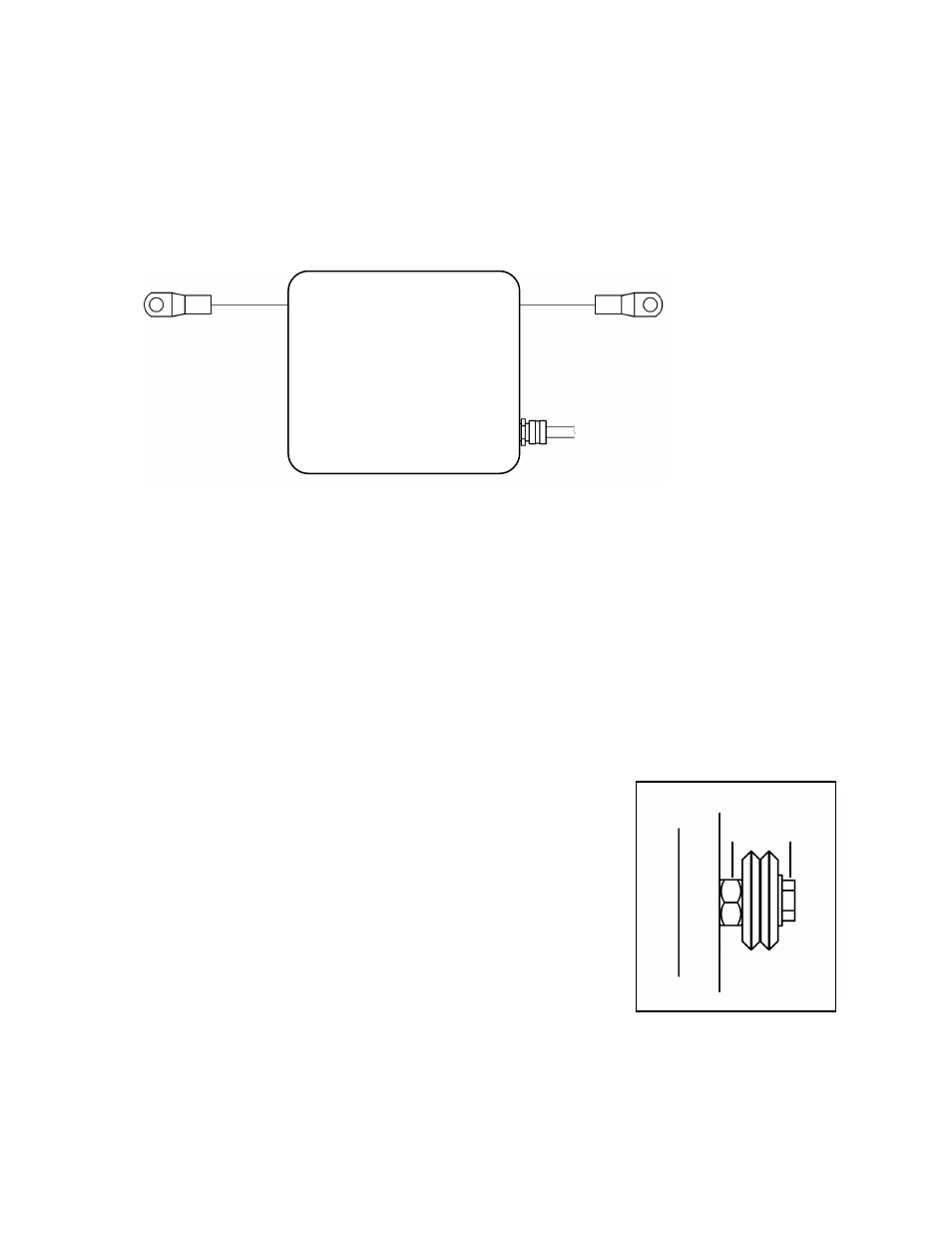
CONNECTING THE SHUNT
Connect the shunt “in-line” on the welding power source ground cable. The shunt’s positive lead and
the signal output cable are located on the same side of the enclosure. For a positive electrode, this
lead should be connected to the work piece.
POWER SOURCE
Use only constant voltage type power sources with this welding device. If using a multiple process
power source, be sure that it is set for constant voltage output as per the instructions in the power
source manual. Set the power source polarity switch properly or connect the electrodes and work
leads for the correct electrode polarity.
to Work Piece
to Control Unit
to Power Supply
Shunt & Filter
Assembly