Operating instructions – BUG-O Systems BEAM BUG III User Manual
Page 17
8
17
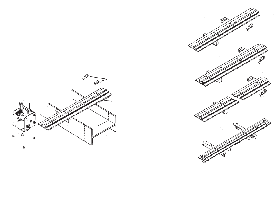
ARR-9114
Beam Rail for square cutting beams ONLY.
Capacity: Cuts 2"-18" (50-450 mm) flanges and 14"
(350 mm) webs.
Length: 46-1/2" (1180 mm)
Net Wt.: 18 lbs. (8 kg)
Shipping Wt.: 28 Lbs. (13 kg)
ARR-9214
Swivel-Mounted Beam Rail for
straight, bevel, coping and miter cuts on
the web. (May also be used for miter cuts
on the flanges by rotating the beam).
Capacity: Cuts 2"-18" (50-450 mm)
flanges and 36" (900 mm) webs.
Miter cuts on 14" (350 mm) webs.
Length: 72" (1830 mm)
Net Wt.: 28 Lbs. (13 kg)
Shipping Wt.: 41lbs. (18 kg)
ARR-9236
Swivel-Mounted Beam Rail, same as
above but, with greater capacity:
Cuts: 2"-18" (50-450 mm) flanges
and 66" (1675 mm) webs.
Miter cuts on 36" (900 mm) webs.
Length: 102" (2590 mm)
Net Wt.: 36 lbs. (16 kg)
Shipping Wt.: 51lbs. (23 kg)
ARR-9045
Adjustable Beam Rail, includes two (2)
squaring bars and adjustable locks for
miter cutting flanges 0
0
-45
0
to 14"
(355 mm) wide, and webs;
0
0
-13
0
to 36" (915 mm) wide
0
0
-45
0
to 24" (610 mm) wide
36" (915 mm) of travel.
Net Wt.: 50 lbs. (23 kg)
Shipping Wt.: 75 lbs. (34 kg)
ARR-9046
Adjustable Beam Rail, similar to above
but, cuts webs;
0
0
-34
0
to 60" (1524 mm) wide.
0
0
-45
0
to 50" (1270 mm) wide.
72" (1830 mm) of travel.
Net Wt.: 65 Lbs. (30 kg)
Shipping Wt.: 90 Lbs. (41 kg)
SQUARE CUTS
1. Accurately mark the line where the cut will be made on the beam. Install Beam
Rail (N) approximately 8" (200 mm) behind this line (The rack teeth on
beam rail should face away from line). Make sure beam is free of dirt, chips,
and other debris which would prevent magnets or beam rail from setting
flat and result in a crooked cut. Place
Beam Rail (N) on the beam and
adjust, making sure it is parallel to the layout line (parallelism is most
important). Next install the two
“C” Clamps (Z) to hold down end opposite
magnets.(Ref. Fig. 2)
2. Depress Clutch Knob (R) and slide BEAM BUG III onto beam rail.
NOTE: Clutch Knob (R) faces away from rack teeth on beam rail.
Be sure all four wheels are on the rail before starting. (Ref. Fig. 2)
OPERATING INSTRUCTIONS
3. In case Torchholder (H) was bumped during shipment, check to see
that it is parallel to the rail as follows (Ref. Fig. 3):
A. Lock Rackholder (I) on Rack (G) [or torchholder assembly].
B. Swing Torch (BB) to a horizontal position and measure distance
from
Torch Tip (DD) to edge of Rack (N).
C. Swing Torch (BB) 180
0
and measure distance from
Torch Tip
(DD) to edge of Rack (N) on other side.
D. These two measurements must be equal. If they are not, loosen
Socket Head Cap Screw (T) and nudge Torchholder (H) around
the vertical axis, and retighten
Clamp Knob (U) when the mea-
sured distances (repeating Steps B and C) are equal.
Figure 2
Z
N
E
R