Connecting multiple me-1s, Phantom power, Dc power – Cloud Electronics ME-1B User Manual
Page 4: Me-1 series installation guide v2.0 4, Cloud electronics limited, Cloud electronics usa
ME-1 Series Installation Guide v2.0
4
Connecting Multiple ME-1s
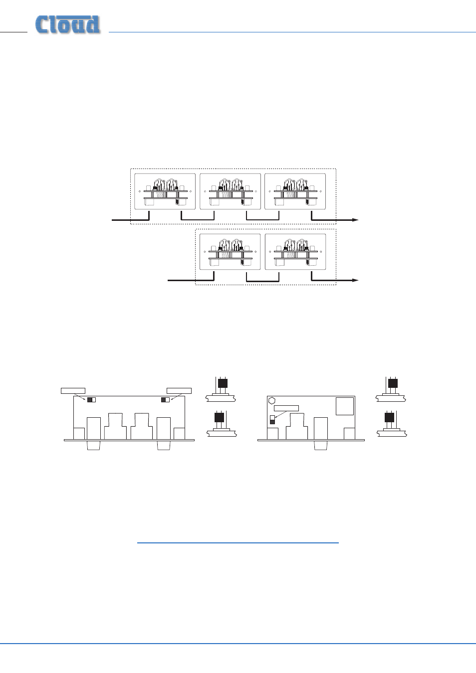
Multiple ME-1s may be “daisy-chained” together to provide additional input points, normally in the same zone. Signals applied to
modules wired in this way will be summed together and fed to the DCM1 Microphone Input to which the “first” ME-1 in the
chain (that whose OUTPUT socket is connected directly to the DCM1). An internal gating circuit on each module automatically
“disconnects” any chained modules which are not in use, to minimise noise contribution. All microphones plugged into ME-1s on
such a chained system will be summed together into one mono signal.
Multiple ME-1s may be daisy-chained together by connecting the LINK RJ45 socket on the first ME-1 to the OUTPUT socket on
the second ME-1, and so on, as shown below.
To DCM-1
Microphone Inputs
(one per zone).
ZONE 1
ZONE 2
Additional
input plates
Additional
input plates
ME-1
OUTPUT
LINK
ME-1
OUTPUT
LINK
ME-1
OUTPUT
LINK
ME-1
OUTPUT
LINK
ME-1
OUTPUT
LINK
Phantom Power
12 volt phantom power may be enabled on either input channel. The installer should determine what type of microphone(s)
are to be used with the ME-1 before setting these, as inadvertently-applied phantom power can damage some types of dynamic
microphone.
Phantom power is enabled by moving the two jumpers on the rear pcb, as shown below.
(REAR VIEWS)
Phantom power OFF
Phantom power ON
(TOP VIEW)
Channel 1
Channel 2
(SIDE VIEWS)
Phantom power OFF
Phantom power ON
(BOTTOM PCB)
Jumper
ME-1 and ME-1A
ME-1M
DC Power
The ME-1 is powered from the DCM1’s MICROPHONE INPUTs via the Cat 5 connection. The ME-1 and ME-1A consume 43 mA
of current at both +12 V and -12 V from the DCM1 power supply; the ME-1M consumes 30 mA.
If there is any doubt regarding the DCM1’s spare DC power capacity (as might be the case in a very large system with many CDR-1
remote controls, level restoration relays, etc.), please refer to the DCM1 Installation and User Guide (Appendix; PSU capacity) where
full details of the DCM1’s PSU ratings can be found.
Should you have any questions concerning the installation and connection of the ME-1, please visit where you will find additional technical information.
Cloud Electronics Limited
140 Staniforth Road, Sheffield, S9 3HF. England.
Telephone: +44 (0)114 244 7051 Fax: +44 (0)114 242
5462 Web: www.cloud.co.uk E-mail: [email protected]
Cloud Electronics USA
2065 Sidewinder Drive, Suite 200, Park City,
Utah 84060. United States of America.
Toll Free: 0855 810 0161
Web: www.cloudusa.pro E-mail: [email protected]