System regulator testing, System voltage testing, Figure 5-2: system regulator voltage testing – Codan Radio MT-4E Analog and P25 Digital - Maintenance Guide User Manual
Page 30: Temperature
MAINTENANCE GUIDE | MT-4E ANALOG & P25 DIGITAL RADIO SYSTEMS
Chapter 5: Codan Radio System Testing
Page 22
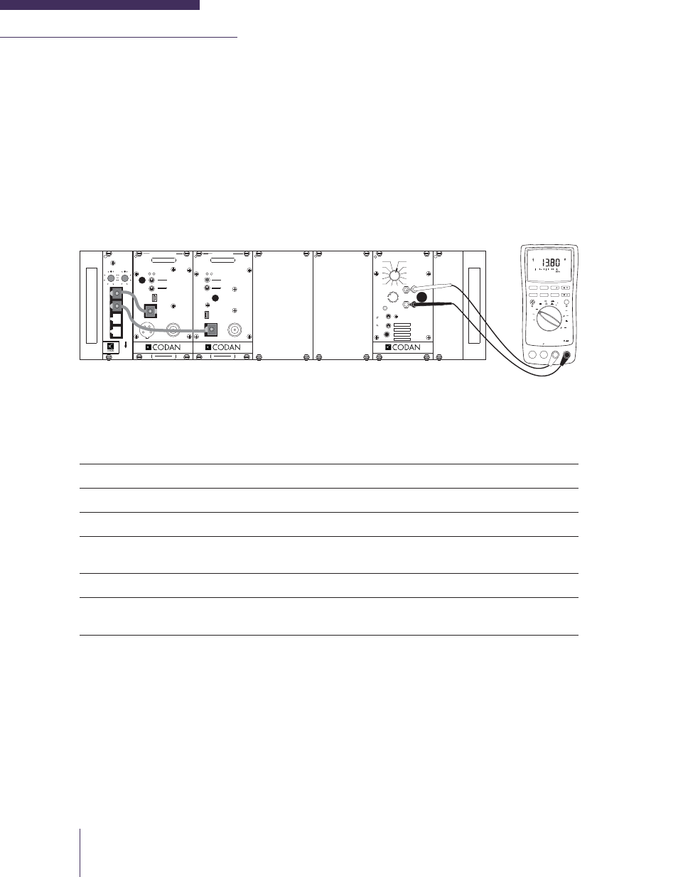
SYSTEM REGULATOR TESTING
System Voltage Testing
The fi rst stage of testing a Codan MT-4E radio system is to perform a basic system check on the supply
and regulated voltages. The System Regulator module is designed with a convenient and easy test
point built into the front panel. This test point allows a technician access to the DC supply and regulated
voltages. Simply connect a standard Digital Volt Meter (DVM) to the METER jacks on the front panel
of the System Regulator as shown in Figure 5-2.
Figure 5-2: System Regulator Voltage Testing
The FUNCTION rotary switch on the front panel of the System Regulator will allow you to test various
points in the radio system. Following is a list of System Regulator rotary switch positions, the functions
they measure and the parameters measured:
1
Supply Voltage
+10 Vdc to +17 Vdc (+13.8 Vdc nominal)
2
+9.5 Volts Regulated
+9.5 Vdc (± 0.1 Vdc)
3
Rx A Audio
Receiver A Audio (NOT Rx Balanced Output)
4
Rx A Carrier Strength
0 Vdc to +5.0 Vdc based on received signal strength
(0 Vdc is a low RF signal level, +5.0 Vdc is high)
5
Rx B Audio
Receiver B Audio (NOT Rx Balanced Output)
6
Rx B Carrier Strength
0 Vdc to +5.0 Vdc based on received signal strength
(0 Vdc is a low RF signal level, +5.0 Vdc is high)
Enter the Supply Voltage and +9.5 Volts Regulated values on the MT-4E Test Sheet. Inject a -100 dBm
carrier signal into the Receiver and record the RSSI Voltage on the MT-4E Test Sheet. Enter the Date,
Firmware Versions and Serial numbers of the Receivers and Transmitters on the MT-4E Test Sheet.
The Firmware Version and Serial Number can be found by connecting the RSS and clicking on Rx ID
or Tx ID. The Serial Numbers can also be found on the side of the modules.
The standby current draw of the radio system should be measured for battery / solar powered systems.
Connect an ammeter to the power input line and measure the standby current draw and transmit current
draw of the system. Enter the Standby Current Draw and Transmit Current Draw readings on the MT-
4E Test Sheet. The maximum standby and transmit current draw is dependent on the radio system
(number and class of receivers, transmitter output power, amplifi ers, auxiliary equipment, etc.).
MIN MAX
HOLD
REL
% ms
Hz
RANGE
dB
dB
ac+dc
ac+dc
ac+dc
ac+dc
F
nS
mA
mA
A
mV
V
mV
V
OFF
C
A
A
A
A
mA
COM
V
TEMPERATURE
A
MIN MAX
HOLD
REL
% ms
Hz
RANGE
dB
dB
ac+dc
ac+dc
ac+dc
ac+dc
F
nS
mA
mA
A
mV
V
mV
V
OFF
C
A
A
A
A
mA
COM
V
TEMPERATURE
A
AutoHOLD
LOGGING
SAVE
CANCEL
FAST MN MX
SETUP
YES
NO
DIGITAL MULTIMETER
CLEAR MEM
VIEW
DC
TRANSMITTER
CNTL
BUS
MIC
RF OUT
A D
ANALOG
DIGITAL
NORM
OFF
KEY TX
MIC MODE
REF
IN
USB
FREQUENCY (MHz)
MADE IN CANADA
MODEL # CODE
RECEIVER
NORM
SQ. DISABLE
OFF
CNTL
BUS
A D
RF N
I
REF
IN
USB
FREQUENCY (MHz)
MADE IN CANADA
MODEL # CODE
VOL
SYSTEM REGULATOR
METER
+
-
MADE IN CANADA
ON
OFF
SPKR
INT
EXT
EXT
SPKR
OFF
POWER
ON
2
1
5
4
3
6
7
8
11
10
9
FUNCTION
12
REPEATER
CONTROL
RX B
TX B
RX A
TX A
PULL DOWN
TO REMOVE
9
5
3
7
11
15
9
13
3
7
11
15
SWITCH A
SWITCH B