Code CR8000 Quick Start User Manual
Cr801# - l0# - mt# - d# - c
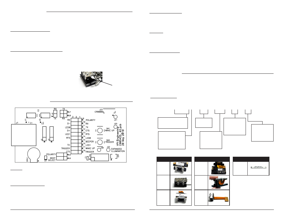
Flex Cables
D0 -
Standard
D1 -
Reverse
D2 -
Center-
line
Mounting Types
MT1 -
Tabs
MT2 -
Bracket
MTX - No
Tabs
Development Kit Features
Ordering Instructions
2
3
Communication Modes
The CR8000 is defaulted to the communication mode ordered: USB (for CR8011-DK0) or
RS232 (for CR8012-DK1).
For USB communication mode: Once the Affinity cable is attached to the Development Kit,
simply plug the USB cable into a USB port on the computer. There is no need to power off
the computer. Once connected the CR8000 will power on and beep. The input voltage range
is 4.5 to 5.5V.
For RS232 (serial) communication mode: Once the Affinity cable is attached to the
Development Kit, simply plug the RS232 cable into a serial port , and the power supply into
the Affinity cable and plug the power adapter into a wall socket. Once connected the CR8000
will power on and beep. The input voltage range is 3.3V to 5.5V. The serial mode also
supports a low power sleep mode of operation.
Computer Host Interface
J1 is the RJ-50 connector which carries both USB and RS-232 signals to an external interface.
J10 and J12 have been preset to match the Affinity cable shipped with the Development Kit.
Please refer to the CR8000 Integration Guide for more information.
Indicators
The development board includes a speaker (SPK1) for audible indication as well as a bi-
color LED (D1) for visual indication. Please refer to the CR8000 Integration Guide for more
information.
Configuration Jumpers
A group of jumpers allow the development board to re-configure and access different features
of the CR8000. The CR8000 host port configuration can be changed via the jumper block J9-
J18. Please refer to the CR8000 Integration Guide for more information.
Interface
J23 connects to the CR8000 decoder board host interface. Please refer to the CR8000
Integration Guide for more information.
Trigger/Wake Up Switches
SW1 will bring the unit from sleep mode to active mode and SW2 will initiate a bar code read.
Please refer to the CR8000 Integration Guide for more information.
Either a CR8000 Scan Engine or CR8000 Development can be ordered, depending on the SKU
requested. Such requests can specify the mounting preference - tabs, blind through holes, or
mounting brackets, etc. To order, please contact [email protected].
CR8000 Scan Engine
Code Reader Type
CR801- CR8000 Scan Engine
CR801# - L0# - MT# - D# - C#
Mounting Type
MT1 - Tabs
MT2 - Bracket
MTX - No Tabs
Communication/
Connection Type
1 - USB
2 - RS232, Serial TTL
Focus
L00 - Standard
Flex Cable
D0 - Standard
D1 - Reverse
D2 - Center-line
Ribbon Cable
C800 - 2”
C801 - 6”
C802 - 12”
Ribbon Cables
C800 - 2”
C801 - 6”
C802 - 12”
Note: If the Development Kit does not power
on, disconnect and re-seat the connections
of the white Ribbon Cable to the Decode and
Interface boards. (Figure 3)
Ribbon Cable
Figure 3
Note: The Development Kits
use a ribbon cable (FFC) with
contacts on opposite sides of
the cable. The Standard ribbon
cables (above) and those
commonly available, have
contacts on the same side.