Code CR1200 Quick Start User Manual
Targeting, Changing or adding cables
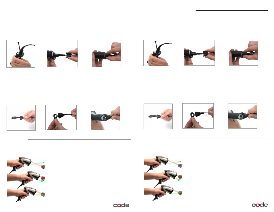
CR1200/CR1210’s unique targeting function uses two converging targeting LEDs to guide
the user to optimal reading range.
Too far from code
Too close to code
Optimal distance from code is
3.8” (9.7 cm) for the CR1200.
Optimal from code is 2.3” (5.8 cm)
for the CR 1210.
Targeting
Should you need to change a cable on the CR1200/CR1210, first, unscrew
the two screws in the cable clip (Figure 2). Slide the cable clip away from the reader
(Figure 3). A spacer was placed between the cable clip and the reader handle. Be sure to
remove and keep track of the spacer. Remove the cable from the reader by pulling back
on the 8-pin DIN connector (Figure 4).
Changing or Adding Cables
Figure 2
Figure 3
Figure 4
Figure 5
Figure 6
Attach the new cable by sliding the cable clip onto the cable (Figure 5) and then sliding it
up to the end of the cable. Snap the spacer onto the end of the cable (Figure 6). Align
the 8-pin DIN connectors. Firmly press the cable (with cable clip and spacer) into the
bottom of the reader handle (Figure 7). Place and secure the screws into the cable clip
attachment alternating between the right and left screw until fully seated. Screws shall be
tightened to a torque setting of 1 inch-lbs.
Note: Do not over-torque screws.
Figure 7
© 2012 Code Corporation. All rights reserved. www.codecorp.com
© 2012 Code Corporation. All rights reserved.
www.codecorp.com