A.3 scenario 2: marginal interference – Comtech EF Data MCED-100 User Manual
Page 89
MCED-100 MetaCarrier Embedding Device
Revision 1
Appendix A
MN-MCED100
A–3
A.3
Scenario 2: Marginal Interference
Item
Description
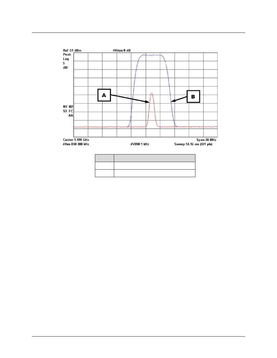
A
“Interfering” 256 ksps Data Carrier
B
“Desired” 3.5 Msps Data Carrier
Figure A-2. Scenario 2 (Marginal Interference)
In the marginal interference scenario shown here in Figure A‐2, the energy of the interfering
carrier is due to cross polarization and is not significant – the 256 ksps (cross polarization)
carrier, as shown, does not have enough energy to completely interfere with the 3.5 Msps
carrier. In most cases, a carrier as small as this would not be detectable, and the only
discernable problem would be where FEC does not compensate for the reduction in Es/No due
to the minor interference.
When the carriers have Carrier ID technology enabled, the MCxD‐100 may be instructed to look
in the spectrum below the composite envelope of the 3.5 Msps carrier to determine if Carrier
IDs are present. Optimally, only a single carrier would be present, but in such interference
conditions, multiple Carrier IDs may be found.
Once an interfering carrier is found, the uplinking station may be contacted and a request made
to disable the identified transmission service.
In a cross polarization scenario, the energy of the cross polarization carrier may be extremely
small, and the desired 3.5 Msps data carrier may be much larger than the cross polarization
component. In this situation, the monitoring station may simply move to the cross polarization
and look directly under the interfering carrier to determine the transmission source.