3 viterbi decoding theory, Rf bb, Figure 4-3. demodulator block diagram – Comtech EF Data SDM-100A User Manual
Page 123
SDM-100A Satellite Modem
Theory of Operation
Rev. 0
4–7
I
A/D
ALIAS
FILTER
AGC
IF FILTER
ALIAS
FILTER
A/D
DIGITAL
DIGITAL
NYQUIST
NYQUIST
Q
90
0
RF
SYNTH
MPC
IF
LOOPBACK
VCO
MPC
DDS
RX DATA
SYNCHRONOUS
DESCRAMBLER
MPC
VITERBI
SOFT DECISION
MAPPING
UNIQUE WORD
DETECTOR
DDS
MPC
RX CLOCK
RR
DELAY
RF
BB
IF INPUT
50 TO 180 MHz
-55 TO -30 dBm
DIGITAL
COSTAS
LOOP
DIGITAL
CLOCK
LOOP
MICRO-
PROCESSOR
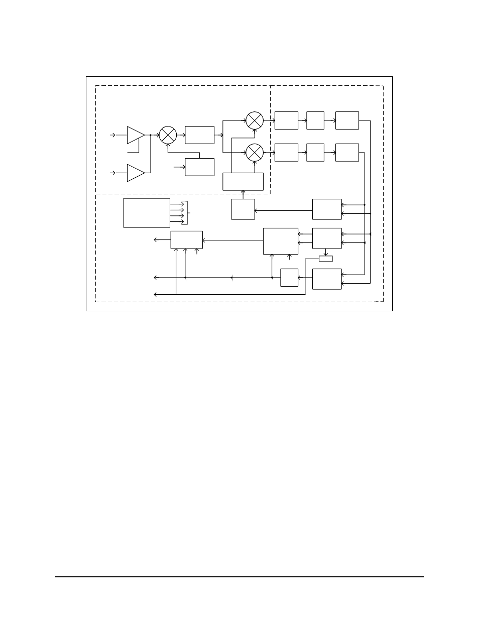
Figure 4-3. Demodulator Block Diagram
4.2.3 Viterbi Decoding Theory
The Viterbi decoder is used in open network applications, typically in IBS or IDR
communication systems. The Viterbi decoder operates in conjunction with the
convolutional encoder in the transmit modem. They correct transmission channel errors
in the received data stream.
Refer to Figure 4-4 for a block diagram of the Viterbi decoder.
The Viterbi decoder processes 3-bit quantized R0 and R1 parallel code bits, or symbols,
from the demodulator. The quantization is 3-bit soft decision in sign/magnitude format.
This is a representation of the data transmitted, corrupted by additive white Gaussian
noise. The decoder uses the code symbols produced by the encoder to determine which
symbols have been corrupted by the transmission channel, and it corrects as many as
possible.
The data signal passes through an ambiguity resolver, which compensates for the
potential 90
° phase ambiguity inherent in a QPSK demodulator. If the decoder is
operating in 3/4 or 7/8 rate, the data signal is then “de-punctured.” The “de-puncture”
pattern is the same as the puncture pattern used in the encoder.