Remote connector and pinouts (j6), Data i/o interface connector (j8), Rf output connector (cp1) – Comtech EF Data SNM-1002 User Manual
Page 38: Rf input connector (cp2), 1 remote connector and pinouts (j6), 2 data i/o interface connector (j8), 3 rf output connector (cp1), 4 rf input connector (cp2)
SNM-1002 LinkSync
Modem
Revision 2
Installation
MN/SNM1002.OM
2–8
2.3.1
Remote Connector and Pinouts (J6)
The remote connector is a 9-pin female D connector (J6) located on the rear panel of the
modem. Screw locks are provided for mechanical security of the mating connector.
The remote connector interfaces the M&C functions to the MIDAS Controller. This is an
EIA-232 DCE interface. Refer to Appendix A for a description of the remote interface.
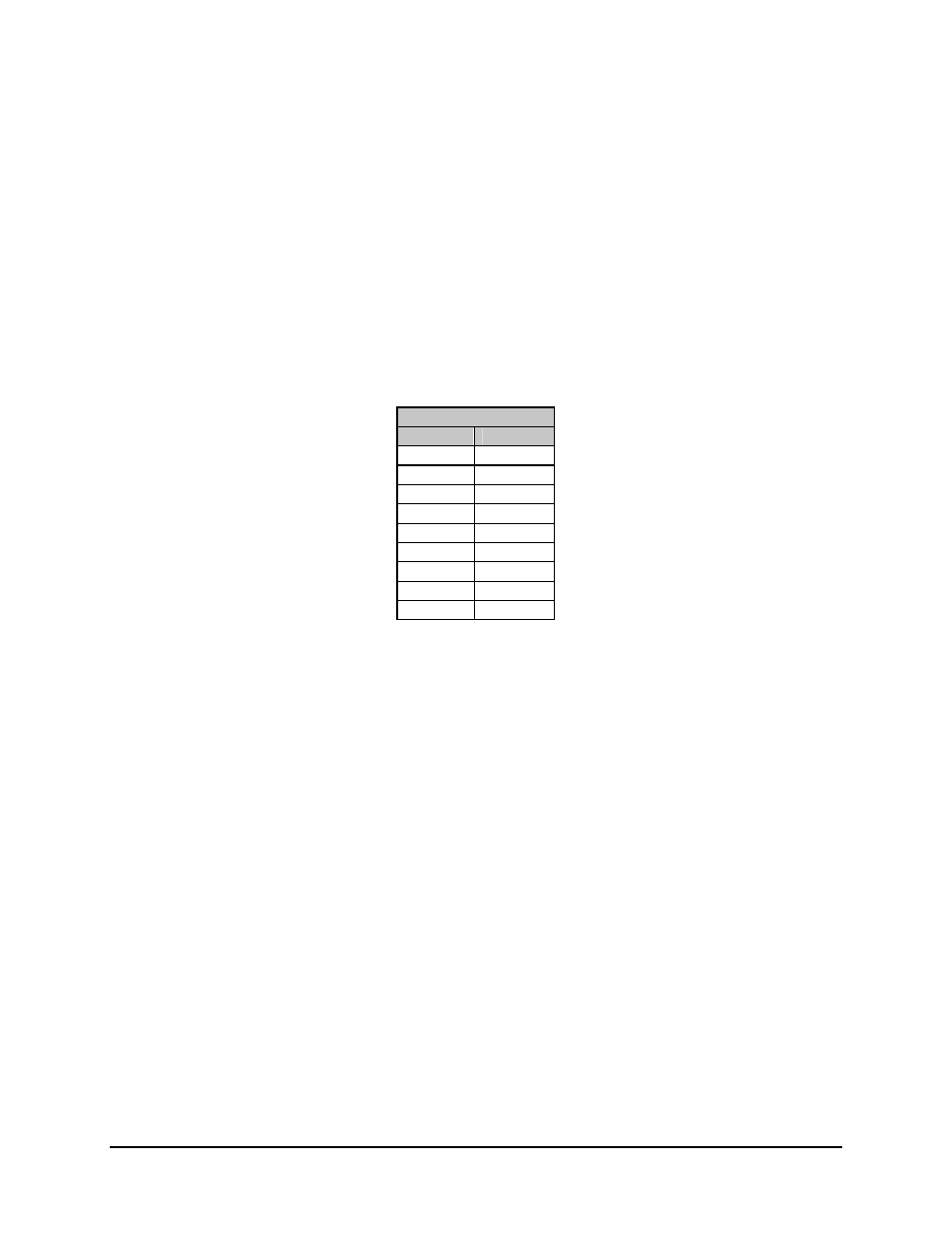
Refer to Table 0-2 for pinout information.
Table 0-2. Remote Connector and Pinouts (J6)
EIA-232
Pin #
Name
1
2 RD
(RX)
3 TD
(TX)
4
5 GND
6 DSR
7 RTS
8 CTS
9
2.3.2
Data I/O Interface Connector (J8)
This connector is only utilized when the modem is operating in a Redundant LinkSync
Configuration. In a Redundant LinkSync
Configuration, the Data I/O cable connects
between an SNM-301 1:1 Switch and J8 of the LinkSync
modem. Refer to Chapter 1,
Figure 1-3.
2.3.3
RF Output Connector (CP1)
CP1 is a BNC connector for the transmit IF signal. The standard output impedance is 75
Ω,
and the output power level is -5 to -30 dBm. In normal operation, the output will be a
QPSK- or BPSK-modulated signal between 50 and 180 MHz, in 1 Hz steps.
2.3.4
RF Input Connector (CP2)
CP2 is a BNC connector for the receive IF signal. The standard input impedance is 75. For
normal operation, the desired carrier signal level should be between -30 and -55 dBm.
Signals between 50 and 180 MHz are selected and demodulated to produce clock and data
at the Data I/O connector.