Comtest Networks 3048 POTS/ISDN Splitter Shelf User Manual
Comtest Networks Communication
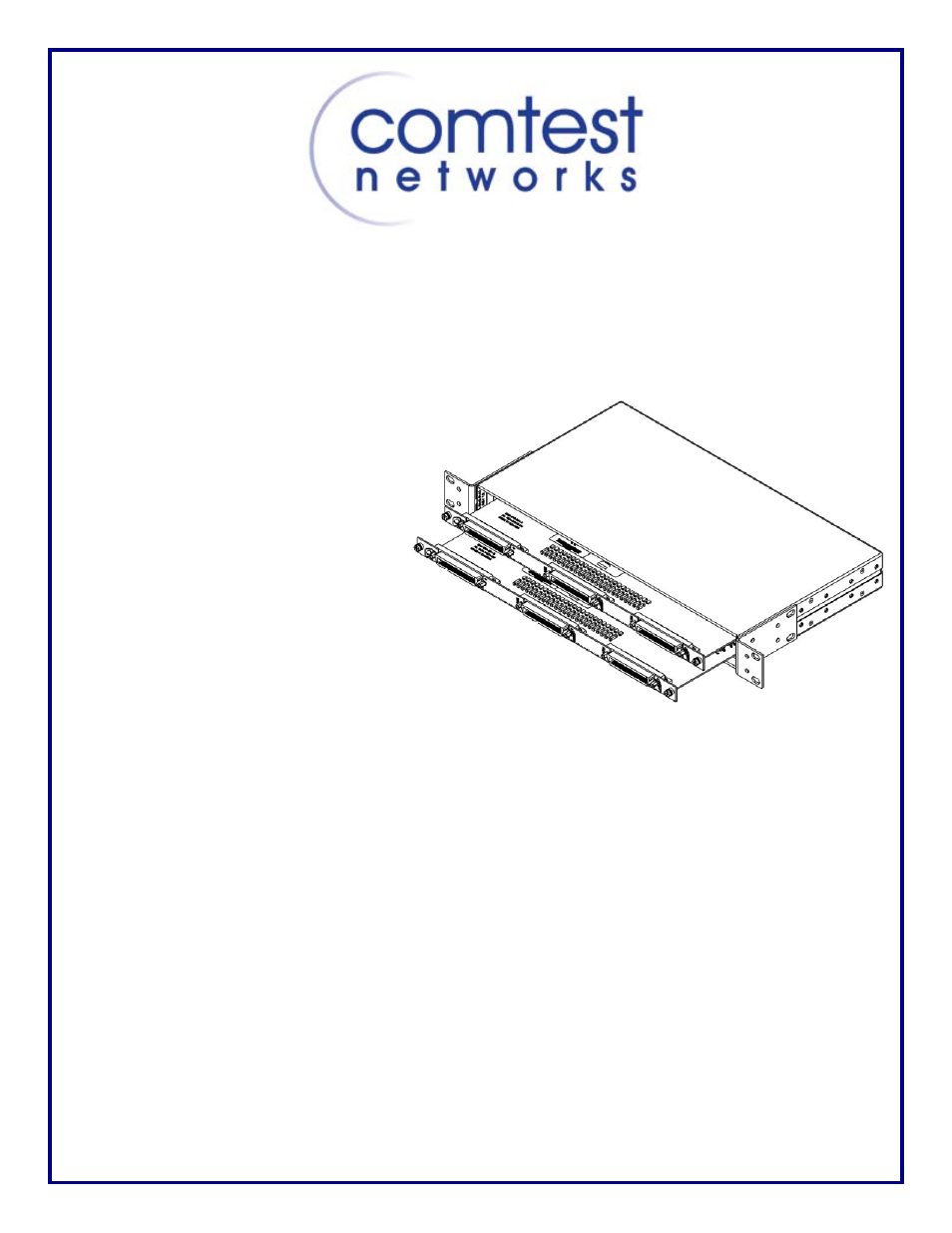
Model 3048 POTS/ISDN Splitter Shelf Installation Guide
Copyright © 2008, Comtest Networks Inc.
This guide provides the basic information required to install the Comtest Model 3048 POTS/ISDN Splitter Shelf
in a Central Office location.
Installation
The 3048 requires 1U (1.75
inches) of rack space. The shelf is
supplied with mounting brackets
and hardware to allow installation
in a 19 inch or 23 inch rack. By
repositioning the mounting
brackets, the shelf can be installed
with the connectors front or rear
facing. With the connectors facing
the front, a depth of 10 inches
would be sufficient to mount the
shelf with cables installed.
Grounding
To comply with the Network
Equipment Building Systems
(NEBS) requirements, a suitable
ground must be provided. Any
holes used for the mounting bracket can be used to provide a grounding connection.
Cabling Overview
The 3048 Splitter Shelf cabling configurations will vary depending on installation locations and the number of
lines supported by the DSLAM. However, the physical interface to the Front Panel connectors are standard 50-
pin RJ-21 type receptacle connectors. Each Splitter card uses 24 pairs of the 25 pairs available on each 50-pin
connector.
Connector Pin Outs
As view from the rear of the shelf:
• xDSL signals to and from the DSLAM enter the 3048 splitter shelf using the left most telephone
connectors, designated ‘DSL’ interface.
• Signals to and from the LINE (outside plant) enter the 3048 splitter shelf using the centre
telephone connectors, designated ‘LINE’ interface.
• Cables to and from the central office switch enter the 3048 splitter shelf via the right hand
telephone connectors, designated ‘PSTN’ interface.
xDSL
Interface
LINE
Interface
PSTN
Interface