Comtest Networks H192 POTS Splitter User Manual
Remote pots splitter installation guide
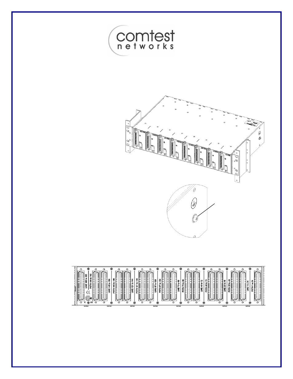
NA-H192 Shelf Back View
Remote POTS Splitter Installation Guide
Copyright © 2007,
Comtest Networks
This guide provides the basic information required to install the H192 POTS Splitter.
Installation
The H192 requires 2U (3.5 inches) of rack
space and is centre mounted. The shelf is
supplied with mounting brackets and hardware
to allow installation in a 19 inch or 23 inch rack.
The H192 must only be installed in restricted
access locations by trained personnel.
Grounding
To comply with the Network Equipment Building Systems (NEBS)
requirements, a suitable ground must be provided. The H192 can
be grounded to the rack through a grounding screw on the right
side. Grounding lugs are provided on the rear of the H192 to
provide an accessible termination point for cable shield/25
th
pair
grounds. On the front, pins 25 & 50 (the 25
th
pair) are grounded
internally.
Cabling Overview
The H192 Splitter Shelf cabling configurations will vary depending on installation locations and the number of lines
supported by the DSLAM. The physical connectors are the standard 50-pin Amphenol-type female connectors.
Each Splitter card uses 24 of the available 25 pairs on each 50-pin connector.
The DSL Interface
connectors are front
mounted with the LINE
and POTS Interface
connectors mounted
on the rear of the shelf.
Each cable head should be secured with a tie wrap and the cable head screw.
NA-H192 Shelf Front View
Grounding screw