Bit rate and parity setting, Connection examples, Mounting – Contemporary Control Systems Modbus Cube I/O MR-AI8 User Manual
Page 2: Software description
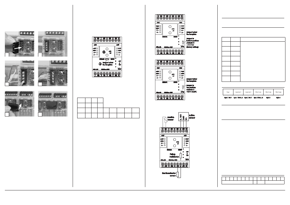
7. Bit rate and Parity setting
The bit rate and parity can be set in the programming mode
when ajumper is plugged behind the front cover of the module.
This jumper is removed in normal mode. A connection to the
bus is not required during bit rate setting.
The bit rate of the modules can be set in the following way:
1. remove the front cover of the module;
2. plug a jumper to the two middle pins of the 4 pole header
between the red and green LED (Á);
3. set the desired parity and bit rate with the address switches
(Â) in accordance to the chart below.
4. switch on the supply voltage of the module; it is now per-
manently saving the bit rate in an EEPROM;
5. switch off the supply voltage of the module;
6. remove the jumper from the header and place the front
cover.
If the settings differ from the settings specified in the chart the
factory setting applies.
Factory setting: 19200 Bd Even
1
8
2
7
4
5
C2
C2
C2
C2
C2
C2
S
S
1
2
3
4
24V
24V
+24V
GND
+24V
GND
ERROR
B +
A -
MR-AI8
B +
A -
BUSY
x1
x10
MODBus RTU
J
15V
24V
Jumper below
the faceplate
Á
Â
C2
6
3
C2
8. Jumper Positions for Voltage feeding of Ac-
tive Sensors
1
8
2
7
4
5
C2
C2
C2
C2
C2
C2
S
S
1
2
3
4
24V
24V
+24V
GND
+24V
GND
ERROR
B +
A -
MR-AI8
B +
A -
BUSY
x1
x10
MODBus RTU
C2
6
3
C2
Jumper below
the faceplate
Jumper in
bottom position
contacts S
=15 V DC
(factory setting)
1
8
2
7
4
5
C2
C2
C2
C2
C2
C2
S
S
1
2
3
4
24V
24V
+24V
GND
+24V
GND
ERROR
B +
A -
MR-AI8
B +
A -
BUSY
x1
x10
MODBus RTU
C2
6
3
C2
Jumper below
the faceplate
Jumper in
top position
contacts S
=24 V AC/DC
1
8
2
7
4
5
C2
C2
C2
C2
C2
C2
S
S
1
2
3
4
24V
24V
+24V
GND
+24V
GND
ERROR
B +
A -
MR-AI8
B +
A -
BUSY
x1
x10
MODBus RTU
J
15V
24V
C2
6
3
C2
Ub
0..10V
GN
D
active
sensor
passive
sensor
Semiconductor
sensor
Pullup
resistance
9. Connection examples
2
1
6. Mounting
Power down the equipment
Mount the module on standard rail (TH35 per IEC 60715 in
junction boxes and/or on distribution panels).
Installation
Electric installation and device termination shall be done by
qualified persons only, by respecting all applicable
specifications and regulations.
Plug in the terminal block for bus connection
4
3
5 mm
6
5
The module can be aligned without interspace. Use the jumper
plug to connect bus and supply voltage when the modules are
mounted in series.
The maximum quantity of modules connected in line is limi-
ted to 15 or to a maximum power consumption of 2 Amps
(AC or DC) per connection to the power supply. For any
similar block of additional modules a separate connection
to the power supply is mandatory.
Connect the cable for bus supply
Mounting in series
10. Software Description
10.1 I/O Commands
„04 (0x04) Read Input Registers“
Request:
Valid Starting Address 0 .. 15
Valid Quantity of Registers
1 .. 16 (1 to 8 inputs)
Response:
Byte Count 2 x Quantity o. R.
Registers Values Quantity o. R x 2 Bytes
Figure 1
Byte 1 Bit 7
Byte 1 Bit 6..0
Byte 2 Bit 7
Byte 2 Bit 6..0
Byte 3
Byte 4
Exponent
Exponent
Mantisse
Mantisse
Mantisse
Sign
Switch
x1
1
2
3
4
5
6
7
8
Bitrate
(Bit/s) 1200 2400 4800 9600 19200 38400 57600 115200
Switch
x10
1
2
3
Parity even odd none
Input
Register Information
1
0-1
Values are supplied in 2 registers (4 Bytes).
2
2-3
Data type in registers can be configured
(see Registers 16 to 23):
3
4-5
Float value
needs 2 registers (fig. 1)
4
6-7
signed int value
is in 1st register
5
8-9
signed int 0
fills 2nd register
6
10-11
Value remains 0 until a measurement takes place
7
12-13
Data types composed from 2 registers start at an even
address
8
14-15
Configuration Registers
Input circuit and measuring range, data type and value unit and
the sensor characteristic for usual temperature sensors are set for
the 8 inputs with the 8 configuration registers.
Register contents is stored in an EEPROM.
Modbus functions:
“03 (0x03) Read Holding Registers” (max. 20 at once)
“06 (0x06) Write Single Register”
“16 (0x10) Write Multiple Registers” (max. 20 at once)
Holding Register 0-15 Offset Register is added to the measured
value in 2 succeeding registers,
(Input 1 = Register 0 - 1)
Float in both or Signed Integer 16 in the
first one, same as for measured value
Holding Register 16-23 Configuration register (EEPROM)
used to set measuring range,
data type of the measured value
(Float / Integer 16),
unit of the measured value and the
sensor characteristic
(Input 1 = Register 16)
Holding Register 24-63 Register for interpolation charts
(EEPROM),
alternately temperature and resistance,
Float in two succeeding registers
Configuration Register for voltage or resistance measurement:
15 14 13 12 11 10 9
8
7
6
5
4
3
2
1
0
0
0
range
number
METZ CONNECT | Im Tal 2 | 78176 Blumberg | Germany | Phone +49 7702 533-0 | Fax +49 7702 533-433
Distributed by RIA CONNECT GmbH and BTR NETCOM GmbH
Mounting instruction see www.metz-connect.com