Crydom One DR Series ATEX User Manual
Installation sheet, Din rail mount, 06 24 d drd x
AC/DC Output Single Channel &
AC Output Dual Channel SSR
INSTALLATION INSTRUCTIONS
Install the relay on the DIN rail (as shown in drawing).
Wire the relay to the input side. AWG #22 minimum,
AWG #16 maximum (0.3-1.3 mm
2
). Temperature rating of 111ºC.
Wire the relay to the output side. AWG #22 minimum
(0.3 mm
2
), AWG #14 (2.1 mm
2
) x 2 or AWG #12
(3.3 mm
2
) x 1 (standed/solid) maximum. Temperature
rating of 111ºC.
Maximum recommended terminal screw torque input
4.4 in-lbs (0.5 Nm) & output 7 in-lbs (0.8 Nm).
If multiple units are installed be sure to follow derating
curves (reverse side of this sheet).
Please read all installation instructions before using SeriesOne DR SSRs.
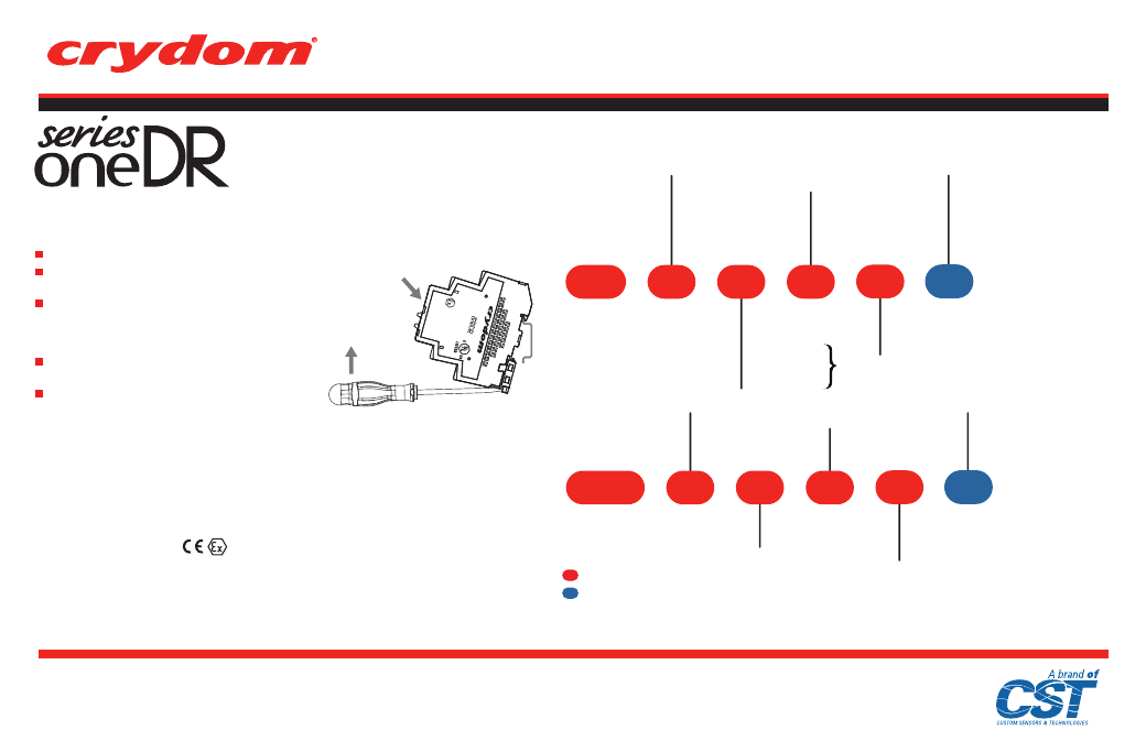
PART NUMBER NOMENCLATURE
Single Channel
Dual Channel
Required for valid part number
For options only and not required for valid part number
(A)
(F,G)
(F,G)
Rev: 041515
SOLID ST
ATE RELA
Y
To install
on DIN rail
To remove
from DIN rail
General Notes
(A)
Not all combinations of ratings are available.
(B)
No grounding wire required. DC inductive loads must be diode suppressed.
(C)
4 Pin connector for dual channel output only. Mating connector: MOLEX 050579404 or equivalent.
(D)
4 Terminal screws Pozidrive #1, 3/16 in (4.8 mm).
(E)
Minimum wire insulation strip length 0.20 in (5.1 mm), maximum 0.28 in (7.1 mm).
(F) F.1
Certified according to EN 60079-0:2012+A11:2013 and EN 60079-15:2010
F.2
Evaluated as equipment II 3 G Ex nA IIC T4 Gc under DEMKO No. 14 ATEX 1201X
F.3
Ambient temperature range -20°C ≤ T
AMB
≤ 40°C
F.4
SPECIAL CONDITIONS FOR SAFE USE:
The system shall be mounted in an ATEX certified enclosure with a minimum ingress protection
rating of at least IP54 as defined in EN60529 and used in an environment of not more than pollution
degree 2. Provision shall be made to prevent the rated voltage being exceeded by the transient
disturbances of more than 140% of the peak rated voltage.
Installation Sheet
DIN Rail Mount
Do not forget to visit us at:
www.crydom.com
Copyright © 2015 Custom Sensors & Technologies. Specifications subject to change without notice.
Series
Operating Voltage
24: 24-280 VAC
48: 48-600 VAC
Rated Load Current
06: 6 Amps
Control Voltage
D: 4-32 VDC
06
24
D
DRD
X
Agency Approvals
X: ATEX II 3G Ex nA IIC T4 Gc
approved
Switching Type
Blank: Zero Voltage Turn-On
R: Instantaneous Turn-On
R
AC
Output
Only
Series
Operating Voltage
06: 1-60 VDC
10: 1-100 VDC
24: 24-280 VAC
48: 48-600 VAC
Rated Load Current
03: 3 Amps
06: 6 Amps
12: 12 Amps
Control Voltage
D: 4-32 VDC
A: 200-265 VAC
B: 90-140 VAC
E: 18-36 VAC
12
06
D
DR
X
Agency Approvals
X: ATEX II 3G Ex nA IIC T4 Gc
approved
Switching Type
Blank: Zero Voltage Turn-On
(AC Output Only)
R: Instantaneous Turn-On
(AC Output, D suffix Only)
R