Crydom HS Series User Manual
Installation sheet, Hs series, Heat sinks & assemblies
Do not forget to visit us at:
www.crydom.com
Copyright © 2014 Custom Sensors & Technologies. Specifications subject to change without notice.
Installation Sheet
Heat Sinks & Assemblies
Rev. 033114
HS Series
Heat Sinks & Assemblies
This installation sheet includes detailed mounting instructions which apply for most Crydom HS Series Heat Sinks &
Assemblies. Be sure to visit the product series' datasheet available at the Crydom website to complement this
information. If you have questions or need additional information please contact Crydom Tech Support.
Please read all mounting instructions before using your HS Series Heat Sinks & Assemblies.
General Notes
(A)
See compatible accessories in corresponding datasheet.
MOUNTING INSTRUCTIONS
Mounting an SSR onto a Heat Sink
Mounting an Assembly on a Panel or DIN Rail
Choose one of the two mounting options according to the selected heat sink or
assembly and follow the instructions.
For Panel Mounting install as shown in fig.3.
Recommended screw size is 8-32 (UNC standard) or M4
(metric).
For DIN Rail Mounting install as shown in fig.4.
Vertical mounting operation is recommended.
Select adequate heat sink (see thermal derating curves in product series’
datasheet).
Be sure to use a thermal pad or thermal compound (0.006 - 0.008 in layer
thickness recommended) between the SSR and the selected heat sink.
SSR mounting slots have a diameter of 0.2 in (5.0 mm). Two screws are needed
to mount a single phase or dual SSR onto heat sink (See fig. 1). HS Series Heat
Sinks include the necessary hardware to mount the relay(s) onto the heat
sink. The number of hardware kits (HK1 or HKM1) included depends upon the
number and type of SSRs possible to install on each heat sink. Recommended
screw size is 8-32 (UNC standard) or M4 (metric) depending on the selected
heat sinks. If you provide your own mounting screws choose screw length
considering the mounting surface hole depth and SSR baseplate thickness.
Before applying full torque tighten down both screws until they contact the
baseplate. Then, tighten them to 20 in-lbs (2.2 Nm).
For optimal thermal performance heat sink fins should be oriented vertically to
promote natural convection airflow. (See fig.2)
fig. 1
SSR mounted
on HS053 heat sink
fig. 2
Maximum heat sink
dissipation on natural convection
(A)
(A)
fig. 3
Panel Mounting
fig. 4
DIN Rail Mounting
HS201DR
SSR
Lug Terminal
Hardware
Kit
Cover
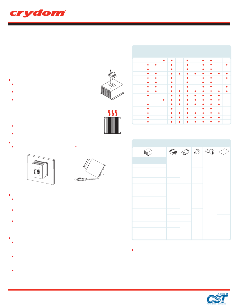
TABLE 2. SSR/Heat Sink Assemblies Compatible Accessories
Thermal Resistance
[ºC/W]
Heat Sink
Part No.
5.0
3.0
2.5
2.0
2.0
1.7
1.5
1.2
1.0
0.7
0.5
HS501DR
HS301
HS251
HS202DR
HS201DR
HS172
HS151DR
HS122DR
HS103DR
HS072
HS053
KS100
KS101
N/A
KS100
KS101
N/A
KS100
KS101
KS103
KS100
KS101
KS103
Solid State
Relay
D2425
HD6025
D2450
HD6050
CC2425W3U
CD4850W4U
D2450
HD6050
CC2450W3U
D2450
HD6050
D2490
HD6090
D53TP25D
D53TP50D
D2490
HD6090
D24125
HD60125
D53TP50D
HKM1
HK1
HK2
HK1
HK1
HK2
HK1
TRM6
TRM1
TRM3/0
Thermal Pad
HSP-1
HSP-2
HSP-3
HSP-5
HSP-1
HSP-2
HSP-3
HSP-5
(A)
Important Considerations
Be sure to use input and output voltages within operating ranges.
LED indicates only input status. It does not represent output status.
Terminals
S1 Generation 4 SSRs
Screw type, touch safe. Input: 6-32, Combo Drive. Output: 8-32, Combo Drive. Maximum screw torque is 15
in-lbs (1.7 Nm) on input and 20 in-lbs (2.2 Nm) on output. See table 1 or table 2 for compatible accessories.
Evolution Dual Series
Screw type, finger proof. Output: 8-32, Combo Drive. Maximum screw torque is 20 in-lbs (2.2 Nm) on output.
See table 1 or table 2 for compatible accessories.
53TP Series
Screw type, finger proof (IP20 only). Input: 6-32, Combo Drive, Output: 8-32, Combo Drive. For IP00 models,
Input: 6-32, Combo Drive, Output: 10-32, Combo Drive. Maximum screw torque is 10 in-lbs (1.1 Nm) on input
and 20 in-lbs (2.2 Nm) on output. See table 1 or table 2 for compatible accessories.
Wire Size
S1 Generation 4 SSRs
Maximum wire size capacity per terminal: input AWG #12 (3.3 mm
2
) x 2, output AWG #8 (8.4 mm
2
) x 2. Choose
wire gauge according to actual load current. For larger wire sizes use lug terminals. See table 1 or table 2 for
compatible accessories.
Evolution Dual Series
Maximum wire size capacity per terminal: output AWG #8 (8.4 mm
2
) x 2, for detail in input terminal see SSR’s
datasheet. Choose wire gauge according to actual load current. For larger wire sizes use lug terminals. See
table 1 or table 2 for compatible accessories.
53TP Series
Maximum wire size capacity per terminal: input AWG #14 (2.1 mm
2
), output AWG #8 (8.4 mm
2
). Choose wire
gauge according to actual load current. For larger wire sizes use lug terminals. See table 1 or table 2 for
compatible accessories.
TABLE 1. Heat Sink Compatible Accessories
(A)
HS501DR
HS301
HS251
HS172
HS122
HS103
HS072
HS053
HS201
Part number
HK1
HK2
HKM1
HSP-1
HSP-2
HSP-3
HSP-5
KS100
KS101 KS300 TRM6
DRK1
TRM1
HS033
HS023
HS101
HS073
HS202
HS151
TRM3/0