A/at, H/ht, D/di – Crydom One DR Series Timer User Manual
Page 2: L/li, Li table 3. led status by function
Rev. 111312
T
C
L
A
T
C
L
H
T
C
L
Y1
B
T
C
L
T
T
T
T
Di
C
L
Y1
T
T
Ac
T=t1+t2+t3
Y1
L
t1
t2
t3
At
C
T=t1+t2+t3
C
L
t1
t2
t3
Y1
Ht
T
C
L
Y1
C
T
C
L
T
T
T
T
A1Y1
D
C
L
Y1
T
T
Bw
C
L
A1Y1
T
on
T
off
T
on
T
off
T
off
L
T
on
C
L
T
off
T
on
T
off
Li
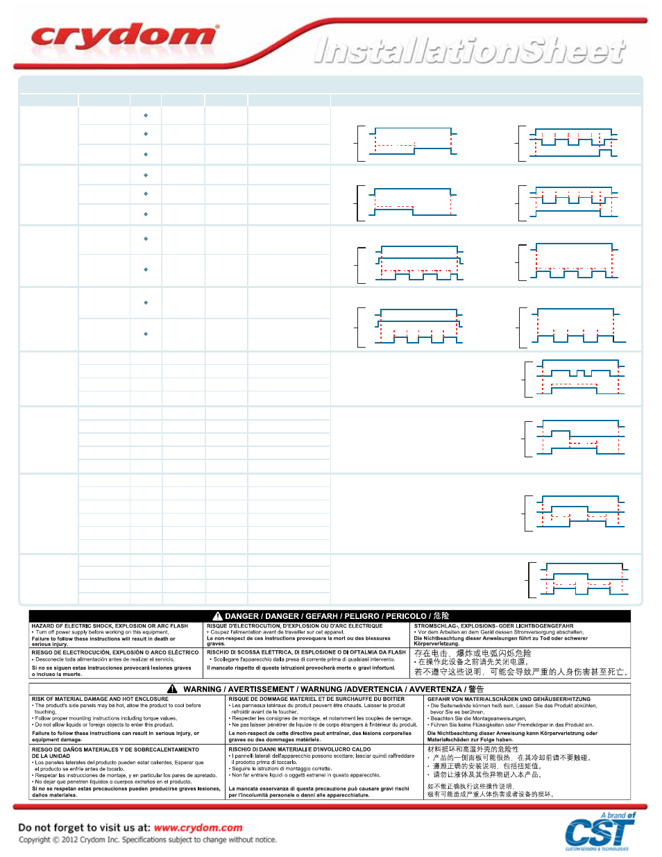
TABLE 3. LED Status by Function
Function
Control Voltage
Y1
Timing
Output State
LED Status
Notes
A/At
Delay On Make
Off
On
On
Off
On
On
On
Off
On
On
On
On
Off
On
On
On
Off
On
On
On
On
On
Off
On
Off
On
Off
On
On
Open
Open
Closed
Closed
Open
Open
Closed
Open
Open
Open
Open
Closed
Closed
Open
Open
Closed
Closed
Open
Open
Off
On
Timed Out
Off
Off
On
Timed Out
Off
Off
Off
On
Timed Out
Off
Off
On
Timed Out
Off
Off
On
Timed Out
On
Timed Out
Off
On
Off
On
Off
On
Timed Out
Off
Off
On
Off
Off
On
Off
Off
Off
On
On
Off
Off
Off
Off
On
Off
Off
On
Off
On
Off
Off
On
Off
On/Off
Off
On/Off
Off
Off
Long Flashes
On
Off
Short Flashes
Long Flashes
Short Flashes
Off
Short Flashes
On
Long Flashes
Short Flashes
Off
Short Flashes
Long Flashes
On
Off
Short Flashes
Long Flashes
Short Flashes
Long Flashes
Short Flashes
Off
Long Flashes
Off
Long Flashes/Short Flashes
Off
Long Flashes/Short Flashes
Short Flashes
H/Ht
Interval
D/Di
Repeat Cycle
L/Li
Repeat Cycle
B
Single Shot
C
Delay On Break
Ac
Delay On Make /
Delay On Break
Bw
At function is identical to the A function except when Y1 is connected to A3 timing is paused. When Y1 is removed timing
resumes until relay times out. To reset timer remove control power.
Ht function is identical to the H function except when Y1 is connected to A3 timing is paused. When Y1 is removed timing
resumes until relay times out. To reset timer remove control power.
Y1 switch can be momentary or maintained to A3. To reset timer
after relay has timed out Y1 has to be opened.
Y1 switch to A3 must be momentary for timing to begin. If during
timing Y1 is closed again the time delay is reset and will begin
again once Y1 is removed. Once timed out timer is reset and
ready for the next cycle.
Y1 to A3 switch can be momentary or maintained. If maintained
until relay has timed out removing it will start timing again. If
momentary and timers has timed out reapplying Y1 will start
timing again.
To start Delay on Make (A) timing connect Y1 to A3 and maintain
until LED is on Solid then to start Delay on Break (c) portion
remove Y1 until relay times out. Removing Y1 During (A) portion or
Connecting Y1 during (c) portion will reset time for that portion.
To select between on time (Di) first or off time (D) first Y1 is connected. Default is On time (Di) first, for Off time (D) first
connect Y1. Equal On/Off time.
To select between on time (Li) first or off time (L) first Y1 is connected A3. Default is On time (Li) first, for Off time (L) first
connect Y1 to A3. Time delay is independent of each other.