Operating modes – Crydom DP Series User Manual
Page 2
Rev. 060211
(F)
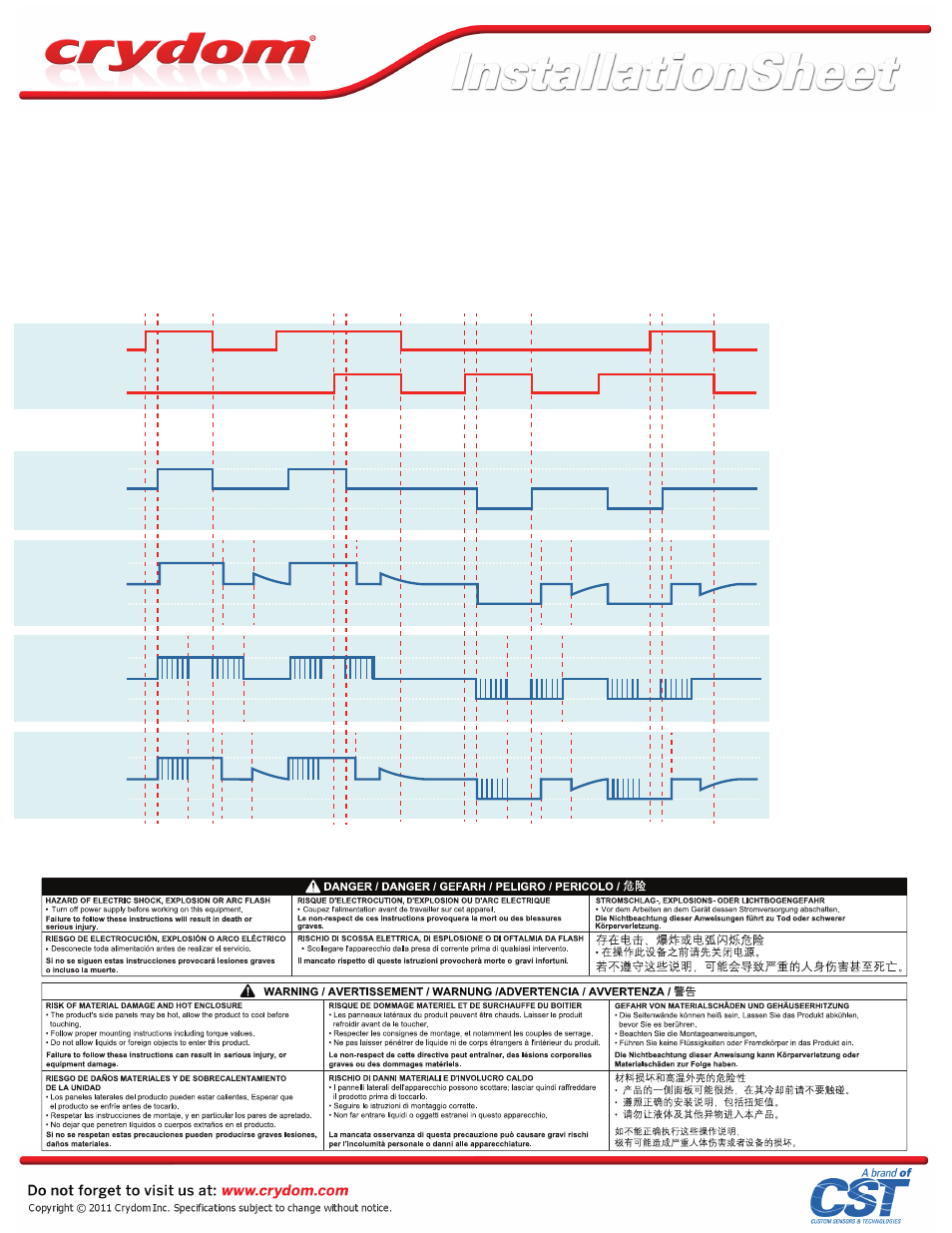
Load voltage signals shown are typical of a DC motor, behavior may change for other load types.
(F)
OPERATING MODES
Start: When either FWD or REV Control signal is applied, and after Control Signal Validation Delay, DC power
supply on terminals 1/- and 2/+ is directly connected to Load at terminals 3/L1 and 4/L2 with a polarity according
to the control signal. The start option can be combined with Stop and/or Dynamic Brake options.
Stop: Load is disconnected from DC power supply. All FET switches (S1, S2, S3 & S4) inside the DP Series SSC are
turned off. This simple Stop option is available only in combination with the simple Start option (suffix Blank).
Soft Start/Ramp Up: It is a modified Start where the DC power supply is connected to the load using a 200 Hz pulse
width modulation with a duty cycle going from 10% to 100%. Soft Start/Ramp Up time is defined by SA, SB and SC
suffixes. After Soft Start/Ramp Up time is elapsed, the Load will remain continuously energized for as long as FWD
or REV Control signal is applied. This option can be combined with Soft Stop/Ramp Down and Dynamic Braking
modes, but not with simple Stop.
Soft Stop/Ramp Down: It is a modified Stop where the DC power supply is disconnected from the Load using a 200
Hz pulse width modulation with a duty cycle going from 100% to 0%. After Soft Stop/Ramp Down time is elapsed,
the Load will remain continuously de-energized waiting for a new FWD or REV Control signal. Soft Stop/Ramp
Down time is tied to Soft Start/Ramp Up time selected by SA, SB and SC suffixes and can be combined with
Soft Start/Ramp Up only.
Dynamic Brake: It could be used as a modified Stop where the FET switches inside the DP Series SSC are
arranged in such a way that they provide a path for the Load Current to keep flowing after the DC power supply
has been disconnected. This mode allows for energy stored in some type of loads to be discharged. i.e. back
EMF on DC motors. Timing for Dynamic Brake is selected by suffixes B2, B5, B8 and B where the latest will
keep the braking or discharging path enabled for as long as FWD and REV Control signals are removed.
Interlock: It will shut down all FET switches inside the DP Series SSC within 0.2 sec after both control signals
FWD and REV are applied at the same time. An Interlock condition will trigger a modified Stop such as Soft
Stop/Ramp Down or Dynamic Brake whenever an option has been selected.
Int : Interlock
t : Control Signal Validation Delay
= 0.2 sec, except for
Start / Stop (0.025 sec)
t
1
: 0.15 sec Break-before-make
delay
t
B
: Dynamic Brake time
B2: 0.2 sec
B5: 0.5 sec
B8: 0.8 sec
B: Continuous
t
SP
: Soft Stop/Ramp Down time = t
ST
t
ST
: Soft Start/Ramp Up time
SA: 0.2 sec
SB: 0.5 sec
SC: 1 sec
V
DCS
: VDC power supply
V
FWD
: Forward Control Signal
V
REV
: Reverse Control Signal
Start
Stop
DP4R60xxx
t
Int
t
t
t
Int
S1, S4
3 / L1 = +
4 / L2 = +
S1, S4
S2, S3
S2, S3
0
+ V
DCS
- V
DCS
Start
Dynamic Brake
DP4R60xxxBx
S1, S4
S3, S4
0
+ V
DCS
- V
DCS
Soft Start/Ramp Up
Soft Stop/Ramp Down
DP4RSx60xxx
0
+ V
DCS
- V
DCS
Soft Start/Ramp Up
Dynamic Brake
DP4RSx60xxxBx
S1, S4
S3, S4
0
+ V
DCS
- V
DCS
Control Signals
Load Voltage Signals
Forward Control
Reverse Control
0
+ V
FWD
+ V
REV
0
t
B
t
B
t
1
t
1
t
1
t
1
t
t
t
t
Int
Int
t
SP
t
ST
t
ST
t
SP
t
S1, S4
S1, S4
S2, S3
S3, S4
t
t
t
Int
Int
t
1
t
1
t
1
t
1
t
B
t
B
t
ST
t
ST
t
t
t
t
Int
Int