Crydom DRS Series User Manual
Installation sheet, Drs series, Accessories
Do not forget to visit us at:
www.crydom.com
Copyright © 2014 Custom Sensors & Technologies. Specifications subject to change without notice.
Installation Sheet
Accessories
DRS Series
DIN Rail Mountable Sockets
FEATURES
PART NUMBER NOMENCLATURE
The DRS Series provides a convenient and easy way to install most of the Crydom single-in-line solid
state relays on a standard DIN rail base. This product family offers both the preassembled SSR / Socket
sets (DRA) and ”socket only“ (DRS) options. Both are available in either single or four channel versions.
For complete assembly part numbers and availability, see DRA Series at www.crydom.com.
10 mm Single channel and 44 mm Four
channel DIN rail mount sockets available.
Input status LED for either 3 to 15 or 15 to
32 VDC control applications.
Cage style screw terminals for easy and
reliable wire connection.
Socket clip fits all standard 35 mm DIN rail
profiles.
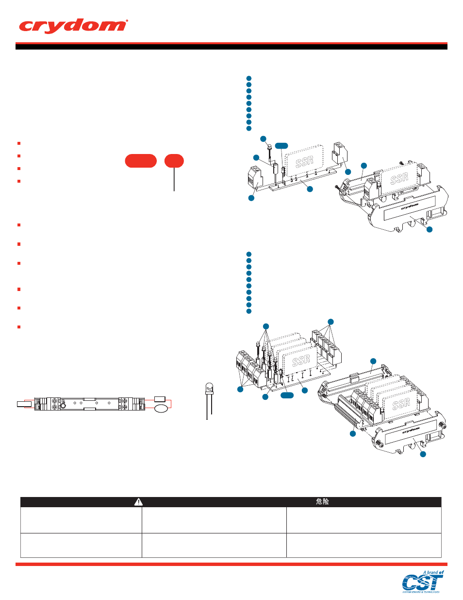
SINGLE CHANNEL SOCKET
(E)
List of parts included in the DRS1 kit
Printed circuit board
Housing - right side (includes 2 screws)
Housing - left side
Green LED
LED standoff
Resistor 1 K Ω, 0.25 W (brown-black-red)
Resistor 4.7 K Ω, 0.25 W (yellow-violet-red)
Output terminal block (marked 1 & 2)
Input terminal block (marked 3 & 4)
Quantity
1
2
3
4
5
6
7
8
9
1
1
1
1
1
1
1
1
1
4
8
1
9
5
6 or 7
2
3
DRS1
FOUR CHANNEL SOCKET
(E)
List of parts included in the DRS4 kit
Quantity
Printed circuit board
Housing - right side (includes 2 screws)
Housing - left side (includes 2 screws)
Profile extrusion
Green LED
LED standoff
Resistor 1 K Ω, 0.25 W (brown-black-red)
Resistor 4.7 K Ω, 0.25 W (yellow-violet-red)
Output terminal block (marked 1 & 2)
Input terminal block (marked 3 & 4)
1
1
1
1
4
4
4
4
4
4
1
2
3
4
5
6
7
8
9
10
9
5
10
1
6
7 or 8
2
3
4
DRS4
ASSEMBLY INSTRUCTIONS
Insert and solder each component as noted below including the selected SSR. Components are
placed such that their leaded ends exit the board on the side with the copper circuit traces. Crydom
recommends use of RoHS compliant solder.
The LED input status indicator plastic standoff should be installed on the LED leads prior to insertion
in the PC board. Observe LED lead polarity (see below LED diagram to determine lead polarity), and
place the corresponding LED leads in the holes using the (+) mark on the PC board as reference.
The input terminal block (marked 3 & 4) is placed in the holes on the PC board adjacent to the LED
with its wire entry openings facing outward toward the end of the board. The output terminal block
(marked 1 & 2) is placed in the holes on the opposite end of the PC board also with its wire entry
openings facing outward toward the end of the board.
Select and install the correct resistor for the SSR control voltage range (see instructions below on
resistor selection). The resistor should have one of its leads bent at 180º over its body such that each
lead can be placed through the holes in the PC board adjacent to the LED input status indicator.
Insert the SSR leads into the PC board and solder to the board. Care should be taken to place the
SSR as near to perpendicular to the PC board as possible so as not to create an interference with
adjacent assemblies when installed on the application DIN rail.
The final step is to place the PC board with soldered components into the plastic housing. The PC
board assembly must be placed in the housing pieces as shown in the assembly diagrams. Note: for
the 4 channel assembly, there is an additional extruded plastic piece that supports the board. The
PC board assembly should be slid into the slots in this supporting piece before attaching the right and
left side pieces. Caution!: do not over tighten the screws attaching the side pieces. Recommended
torque is 6 to 8 in-lbs (0.7 to 0.9 Nm).
RISQUE D'ELECTROCUTION, D'EXPLOSION OU D'ARC ELECTRIQUE
•
Coupez l'alimentation avant de travailler sur cet appareil.
•
在操作此设备之前请先关闭电源。
HAZARD OF ELECTRIC SHOCK, EXPLOSION OR ARC FLASH
•
Turn off power supply before working on this equipment.
Le non-respect de ces instructions provoquera la mort ou des blessures
graves.
Failure to follow these instructions will result in death or
serious injury.
Il mancato rispetto di queste istruzioni provocherà morte o
gravi infortuni.
Si no se siguen estas instrucciones provocará lesiones graves
o incluso la muerte.
Die Nichtbeachtung dieser Anweisungen führt zu Tod oder schwerer
Körperverletzung.
STROMSCHLAG-, EXPLOSIONS- ODER LICHTBOGENGEFAHR
•
Vor dem Arbeiten an dem Gerät dessen Stromversorgung abschalten.
RISCHIO DI SCOSSA ELETTRICA, DI ESPLOSIONE O DI OFTALMIA DA FLASH
•
Scollegare l'apparecchio dalla presa di corrente prima di qualsiasi intervento.
RIESGO DE ELECTROCUCIÓN, EXPLOSIÓN O ARCO ELÉCTRICO
Desconecte toda alimentación antes de realizar el servicio.
存在电击、爆炸或电弧闪烁危险
若不遵守这些说明,可能会导致严重的人身伤害甚至死亡。
DANGER / DANGER / GEFARH / PELIGRO / PERICOLO /
(A)
The temperature of the SSR pins must not exceed 260ºC/ 500ºF for more than 3 seconds, with an allowable iron temperature of 350ºC / 662ºF to prevent possible damage
to the components during assembly or repair.
(B)
Wiring diagram is identical for each individual section whether it is a single or four channel assembly.
(C)
Maximum output rating for DRS Series sockets is 300 VAC / 8 Amps regardless of chosen SSR. Vertical mounting operation is recommended.
(D)
For AC loads, the AC line can be wired to either SSR/socket terminal 1 or terminal 2. The AC load may also be wired on either the line or neutral side of the SSR. For DC loads, the proper polarity must be observed for the power supply,
load and SSR/socket with terminal 1 being positive with respect to terminal 2.
(E)
Use 1 K Ω (brown-black-red) resistor for applications with control voltage range between 3-15 VDC and 4.7 K Ω (yellow-violet-red) resistor for applications with control voltage range between 15-32 VDC. LED status indicator is not
required for proper function of the SSR and may be omitted. No resistors are needed when LED is not installed. For AC input SSR control applications LED status indicator and resistor must not be used.
(F)
SSR(s) purchased separately.
WIRING DIAGRAM
(B, C)
LED DIAGRAM
+ -
Control
Load
(D)
Power
1
2
1
2
3
4
3
4
INPUT
OUTPUT
(+) Anode
(-) Cathode
Please read all of the assembly instructions before beginning assembly of the DRS sockets.
Rev: 052214
(F)
(A)
(F)
(F)
(F)
(+ input for DC
control models)
(+ for DC output models)
Series
Number of Channels
1: One channel
4: Four channels
DRS
1