Section 3: wired speed of pitch configurations, 1 interface configurations, Section 3 – Daktronics Radar Gun Speed of Pitch Interface User Manual
Page 11: Wired speed of pitch configurations, Interface configurations
Speed of Pitch Wire Configurations
5
Section 3:
Wired Speed of Pitch Configurations
3.1 Interface Configurations
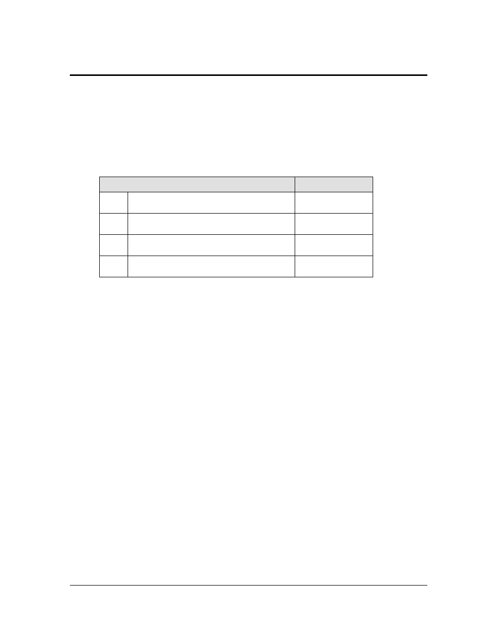
Drawing B-130818 shows the four radar gun configurations that are explained in the
following sub-sections. Each configuration corresponds to a radar gun interface kit from
Daktronics. The table below lists the number, description, and Daktronics part number for
each interface kit:
Interface Kit Description
Part #
#1
Radar gun remote from All Sport;
wired scoreboard feed and current loop RTD
0A-1196-0032
#2
Radar gun remote from All Sport;
wired scoreboard feed and RS-232 RTD
0A-1196-0033
#3
Radar gun within 10' (3 m) of All Sport;
wired scoreboard feed and current loop RTD
0A-1196-0034
#4
Radar gun within 10' (3 m) of All Sport;
wired scoreboard feed and RS-232 RTD
0A-1196-0035
Note: The following setups describe the installation of a JUGS radar gun package.
Installation procedure will vary depending on the gun in use. Any substitute gun
must have the ability to output RS-232 signal to work with this system.
Kit #1: Remote Radar Gun
– Current Loop Scoreboard & RTD
In this configuration, the All Sport console receives speed-of-pitch information from a
remotely-located radar gun. The All Sport then transmits the radar data directly to a
scoreboard via current loop signal. Refer to the instructions below and Drawing B-130818 in
Appendix A to set up the system.
1. Connect the 25-pin to 25-pin signal cable (W-1247) between the J6 port on the back of
the All Sport console and the 25-pin J-box (0A-1067-0056).
2. Route one-pair cable minimum (W-1077) from the 25-pin J-box to the scoreboard, and
another to a
1
/
4
" phone J-box (0A-1091-0227) near the radar gun. Refer to the
installation section of the scoreboard manual for signal connection information.
Note: To send the data to a display controller or DSTI, an additional one-pair cable
minimum may be routed to another signal converter (not included in this kit).
3. Connect the
1
/
4
" phone jack cable (W-1236) between the
1
/
4
" phone J-box and the
signal converter (0A-1065-0173). The cable is cut in half, and the other end is
connected to TB1 on the signal converter (red wire to 1 CL1+, black wire to 2 CL1-).
Plug the signal converter into a 120 VAC power source.
4. Connect the 9-pin to 9-pin cable (0A-1000-0121) between the J1 jack on the signal
converter and the 9-pin plug on the 30' (9 m) data cable (W-2453).