Daktronics Galaxy AF-3500, 3550, GP3, GP4, & SS Display User Manual
Galaxy, Step 1: display mounting, Step 2: connecting power
Galaxy
®
AF-3500, 3550, GP3, GP4, & SS Display Installation Quick Guide
DD1377301 Rev 08
21 October 2013
PO Box 5128 201 Daktronics Drive, Brookings, SD 57006-5128
tel: 800-325-8766 fax: 605-697-4700
www.daktronics.com
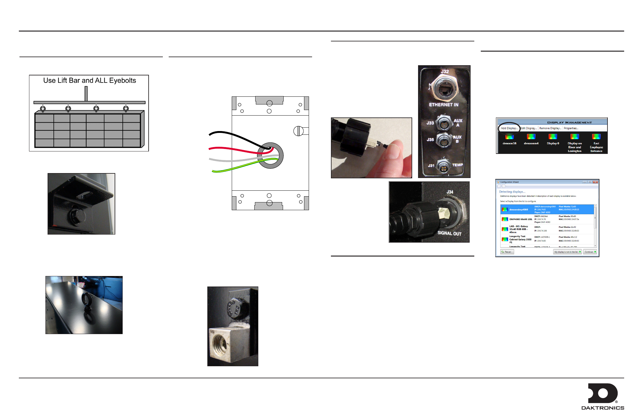
Step 1: Display Mounting
1. Lift the display into position on the support structure.
2. Weld or use
1
/
2
” hardened bolts to secure all clip angles
to support structure
3. Remove crane support from the display.
4. Remove all eyebolts if desired. Seal all of the remaining
holes with silicone approved for use on aluminum.
5. Make sure display structure or shrouding does not block
display ventilation.
Complete these steps in order during the installation process. Refer to the display manual for
additional information.
Step 2: Connecting Power
1. Refer to the label on back of the display or to the display
riser drawing for power requirements. Displays require
either 120 VAC (2 wire + ground) or 120/240 (3 wire +
ground).
2. Wire Line 1, Line 2, neutral, and ground wires according
the shop drawing.
3. Connect grounding electrode to ground lug on each
display face.
4. Test the display ground to ensure it has a resistance-to-
ground of 10 ohms or less.
120/240 VAC Termination
(Box with Cover Removed)
Wiring from power termination
panel inside display
Line 1 – Black
Line 2 – Red
Neutral – White
Ground –
Green/Yellow
Step 3: Communications Installation
1.
Connect the signal cables to the proper Quick-Connect
Jacks on the back of the display.
2. Install quick-connect cable
between Primary display (J-34)
and Mirror display (J-32) when
applicable.
Note: Remove black plugs from
the quick-connect cable before
plugging it into the jack.
Step 4: Turn Display On
1. Turn on power to the display.
2. Observe boot sequence shown on the display to get the
IP Address or DHCP name. The boot time lasts about
three minutes.
Step 5: Venus 1500 Software
Configuration
Refer to the Venus 1500 Help File for additional information.
1. Click Start > All Programs > Daktronics > Venus
1500 V4 to verify Venus 1500 is installed on the control
computer.
2. Click Application button > Configure > Displays to
launch the display configuration wizard in Venus 1500..
3. Click Add Display.
4. Select the customer’s display from the list and click
Continue.
5. Enter the customer’s password on the Authentication
Page. Note: The default password for GP4 displays is
DakPassword!.
6. Click Continue if prompted.
7. Name the display. Click Continue.
8. Select the correct time zone for the display’s location.
9. Click Finish in the Summary window. The new display
appears in the Display Management window.
10. Close the Display Management window to return to the
Home tab view.