Daktronics Rear-Ventilated Galaxy and GalaxyPro Display Ventilation Guidelines User Manual
Rear-ventilated galaxy, And galaxypro, Display ventilation guidelines 1 of 1
Rear-Ventilated Galaxy
®
and GalaxyPro
®
Display
Ventilation Guidelines
1 of 1
DD1954173 Rev 3
15 March 2013
PO Box 5128 201 Daktronics Drive, Brookings, SD 57006-5128
tel: 800-325-8766 fax: 605-697-4700
www.daktronics.com
Ventilation Requirements
Daktronics rear-ventilated Galaxy
®
and GalaxyPro
®
displays rely on
proper ventilation to keep display
components at normal operating
levels. Follow the guidelines
below to allow for proper display
ventilation when designing the
mounting structure.
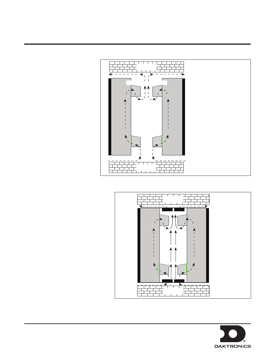
1. Ventilation hoods on the back of
the display must draw in fresh
air from below the display and
exhaust air above the display, as
shown in Figure 1.
Note: Fresh air intake must be
no greater than 120° F
2. Calculate the required square
footage of each opening (x
and y) by measuring the
opening’s length and width and
multiplying the two numbers.
Example: 2’ x 8’ = 16 sq/ft.
Note: Do this calculation for both the
intake at the bottom (y) and the exhaust
at the top (x) for each display to ensure
adequate ventilation.
Note: Make accommodations for
expanded metal or any other covering
placed over air intake (y) or exhaust (x)
openings.
3. Refer to the display shop drawing for
the required square footage for intake
and exhaust openings.
Note: If adequate openings cannot
be provided as required, use fans to
increase airflow as shown in Figure 2.
Filter Maintenance
Ventilation intakes are filtered. Filters,
accessible from the display’s front, must
be cleaned periodically to provide proper
ventilation. Refer to the display manual for the recommended maintenance schedule.
Structure
Structure
x = Required Exhaust Opening
in square feet
Measure:
Opening length and width
Calculate: (Refer to Step 2)
l x w = required square feet
for proper exhaust
(See shop drawing for display size
specific opening requirements)
y = Required Fresh Air Opening
in square feet
Measure:
Opening length and width
Calculate: (Refer to Step 2)
l x w = required square feet
for proper fresh air intake
(See shop drawing for display size
specific opening requirements)
x
x
}
{
}
y
y
{
Di
s
pla
y
Intake
Exhaust
Filter
Di
s
pla
y
F
a
c
e
Di
s
pla
y
Intake
Exhaust
Filter
Di
s
pla
y
F
a
c
e
Figure 1: Ventilation With Adequate Openings Per Shop Drawing Specifications
Fan
Fan
Fan
Fan
Di
s
pla
y
Di
s
pla
y
Intake
Exhaust
Filter
Di
s
pla
y
F
a
c
e
Di
s
pla
y
F
a
c
e
Intake
Exhaust
Filter
Structure
Structure
{
less than y
{
less than y
less than x
less than x
{
{
See shop drawing
for fan airflow
requirements
Figure 2: Ventilating With Fans on a Structure With Restricted Openings