Figure 19: display interconnect -10 – Daktronics Galaxy 46 mm Outdoor Series AF-3400 User Manual
Page 34
A separate manual is provided for explaining the connection to the signal termination
enclosure. There are seven different methods of communication; your manual will
be one of these types:
Communication
Type
Communication
Manual ED#
RS232
ED-14739
RS422
ED-14742
Fiber
ED-14743
Radio
ED-13932
Modem
ED-14744
Ethernet
ED-14745
Fiber Ethernet
ED-14746
3.8 Signal Termination Between Displays (Primary –
Mirror)
Most displays are shipped as either a single Primary
display or two displays in a 2V Primary-Mirror
configuration.
The Primary/Mirror (2V) quick connect cable
terminates signal between two displays. The 6-foot
cable goes from the Signal OUT (J34) on the primary
display to the Signal IN (J32) on the mirror display.
Figure 19 shows the use of one quick connect cable.
Attach the cables so they extend into the side or down,
but never up which would put a strain on the cable.
Figure 19: Display Interconnect
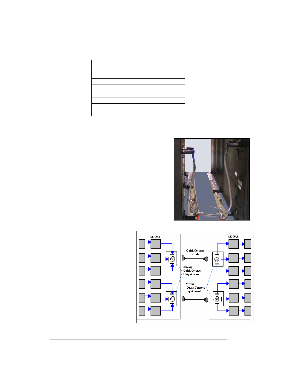
For those displays that are higher than 24 pixels, two
quick connect cables and four quick connect boards
are used as shown in Figure 20.
Figure 20: Quick Connect Cables (48-high display shown)
Displays with 56 and 64 pixels
have 3 quick connect cables.
Make sure the quick connect cable
wire is attached to the structure
and protected from abrasive edges
and as shown in Figure 19. It is
very important to secure the cable
to the structure because it reduces
stress to the PC card jack.
Note: Not all jacks of the
interconnect boards are used in all
circumstances.
Electrical Installation
3-10